Reliability with hearing instruments is one of the top-four critical factors impacting consumer satisfaction with hearing instruments.1 (The other three are benefit at a good value, multi-environmental listening utility [MELU] including hearing in noise, and sound quality).
In a recent article2 on customer satisfaction trends in the US market, customer satisfaction with hearing instrument reliability was shown to have remained static at 72% over the past 10 years. Less than half (48%) of consumers are satisfied with the ongoing expense of hearing instruments (which would include the cost of out-of-warranty repairs). More than half (56%) of current hearing instrument owners cited improved reliability (ie, “hearing aids that do not break down as often”) as a highly sought-after feature in hearing instruments3 while close to three in four consumers (73%) are interested in instruments that are less costly to repair. Finally, about 10% of hearing aids in the drawer are due to “hearing aids that are broken” or “costs of repair” which can be prohibitive for the elderly.4
One of the key reasons for hearing instrument returns for service is receiver failure due to either shock from consumer abuse (eg, dropping on a hard surface while changing the battery) or cerumen build-up in the port of the receiver. Internal data for 2001 indicates that, of all receivers visually examined by the Knowles Product Evaluation Centers after functional failure, 62.3% were found to have either substantially blocked sound ports or significantly damaged sound ports caused by attempts to clear out debris. Furthermore, 20% of all receivers credited under the company’s warranty system failed due to shock damage. Previous research on 7 million receivers and more than 90,000 consumers over a 24-month period determined that receiver returns can be reduced by at least 50% when an effective cerumen management system is used.5,6
While there is a clear solution to the cerumen problem, what can be done to further improve receiver reliability and therefore customer satisfaction with hearing instruments?
A new damping technique has been developed by Knowles that is designed to result in improved shock performance and a reduced vibration signature (and therefore improved gain before feedback) in addition to a greatly reduced likelihood of hearing instrument returns due to cerumen-clogged screen damped receivers (because the screen is no longer necessary). The purpose of this article is to report on the results of a scientifically repeatable experiment that demonstrates the improved robustness in receiver performance due to the new damping procedure.
A New Receiver Design
An alternative to using screens as a means of damping receivers has long been a goal due to the tendency for screens to get clogged with debris and cerumen. An acoustical damping screen is necessary to lower the peaks in the receiver’s output that can rise up to 8 dB or more above the mid-band sound pressure level (SPL).
A new technique has been developed that provides adjustable damping without a screen. Ferrofluid, which is a stable suspension of minute magnetic particles (Fe3O4) in synthetic ester oil, was found to be an effective viscous damper during laboratory tests. The ferrofluid is injected into the gaps between the armature and the magnets in the receiver, where it is retained by the magnetic field (Figure 1).
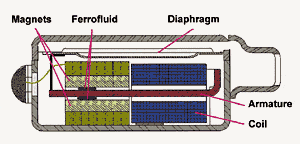
Figure 1. Cross section of a Knowles ED receiver
with a ferrofluid-damped motor (ie, FED receiver).
The fluid decreases the peaks in the acoustical output without affecting the mid-band SPL. The amount of damping can be adjusted over a wide range by selecting the appropriate fluid volume and viscosity. Figure 2 shows the frequency response curves of the ferrofluid damped FED and the traditional ED receivers under constant voltage drive conditions. Ferrofluid offers the advantage of screen damping without the problems associated with cerumen accumulation in the screen, because the screen is no longer necessary. In addition to damping, it protects the armature from shock damage and it reduces the maximum vibration output of the receiver.
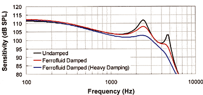
Figure 2. Frequency response curve of FED and ED receivers
connected to 10 mm x 1 mm tubing and a 2 cc coupler under
constant voltage drive conditions.
Durability and Feedback Issues
Hearing instrument users frequently drop their hearing instrument onto hard surfaces (eg, ceramic sink, tiled floor, etc). The hearing instrument should be able to withstand continuous consumer abuse without a noticeable change in the acoustical performance. Due to this, it is important for transducer manufacturers to design receivers that are less susceptible to damage after shock. From the experiment described below, we conclude that ferrofluid damped receivers have improved shock resistance as compared to receivers without ferrofluid, because this method of damping provides protection by “cushioning” the receiver armature during impact.
Feedback in a hearing instrument is problematic because it can limit the maximum gain. Vibrations in the receiver are transmitted through the shell and are picked up by the microphone. As the gain of the aid is turned up, the vibrations get stronger until it becomes an audible signal. Currently, customer satisfaction with feedback and whistling in hearing instruments is only 41%.2 The experimental results described below show that the vibration output is less than the output of receivers without ferrofluid, because the fluid reduces the motion of the armature at resonance.
Method
Shock Performance. In order to characterize impact/shock performance, receivers are subjected to precisely controlled impacts in the Knowles shock rail system. This test system is designed to deliver a repeatable high g-force at impact. Transducer samples are placed into a heavy metal “bob” that slides down a 90-inch rail (inclined at 71.5°) until it strikes a stiff metal plate. Contacting the plate is comparable to hitting a hard floor. The test system is calibrated using an accelerometer to determine the exact deceleration at impact for each drop height. Deceleration is expressed in terms of multiples of g which is the acceleration of a free falling object (ie, g = 9.8 m/s2). The maximum decelerations at impact during the shock test can be as high as 20,000 g.
The purpose of the shock test is to determine the robustness of transducers (ie, failure rates due to impact). The conditions of the test are more extreme than the shock experienced by hearing instruments when they are dropped to the floor; but perhaps not so when you consider the cumulative effect of repeated dropping and abuse. In order to get a better appreciation for the severity of the impact, we can express deceleration in terms of its equivalent weight. For example, a 0.3 gram receiver experiencing a deceleration of 20,000 g has a momentary weight of 6 kilograms (about 13 lbs).
After each drop, the sensitivity, impedance, and distortion are measured. Any change of 3 dB or greater in sensitivity or in impedance is considered a failure. Distortion is measured at 1/2 and 1/3 of resonant frequency where distortion values tend to be highest. Samples fail if the distortion at 1/2 and at 1/3 of resonance is greater than or equal to 20% and 10% respectively. The percent of samples surviving each drop is recorded and plotted as a function of deceleration at impact.
Representative samples (n = 20 each) of receivers were subjected to repeated measure testing in the shock rail system: 1) Ferrofluid receivers with standard damping; 2) Ferrofluid receivers with heavy damping; 3) Representative competitively matched receivers with Type 2 damping. In the drop-test, ferrofluid damped receivers and the competitor’s model with similar size and output were dropped from progressively increasing heights until they failed.
Improving the Vibration Signature of the Receiver. The motion of the armature and diaphragm causes the receiver to vibrate. Therefore vibration is strongest in the direction of this motion, which is perpendicular to the cover. The largest displacement occurs at the resonant frequencies where the excursion of the armature is at its maximum. Ferrofluid reduces the excursion at resonance and therefore reduces the maximum vibration output. The amount of reduction is proportional to the amount of damping in the acoustical output. To prove this, we measured the motion of the receiver perpendicular to the cover as a function of frequency.
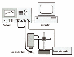
Figure 4. Experimental setup for laser vibration
measurements.
The laser vibration system shown in Figure 4 is capable of extracting information on the linear and rotational motion of the receiver as a function of frequency. For this experiment, the velocity of a point on the cover near the tube was measured. The receiver under test was placed on soft cotton oriented with the cover up. The cotton provides support without affecting the motion of the receiver. The receiver was free to move with no tube or coupler attached. A random noise signal was applied causing the receiver to vibrate.
Results
Shock Performance. The percent of surviving units after each drop is shown in Figure 3. The heavily damped and standard damped FED receivers were two times more likely to survive shock testing than the competitive model. At a height of 38.6 inches, the survival rate of the heavily damped ferrofluid receivers and standard damped ferrofluid receivers were 100% and 95% respectively, compared to 45% for competitive receivers.
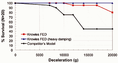
Figure 3. Percent of ferrofluid (FED) receivers and competitive
receivers surviving after each drop relative to deceleration at
impact. Half of the samples were oriented with the cover facing
up and the other half with the cover facing down.
Vibration Signature. For the standard damped and heavy damped ferrofluid receivers (FED), the velocity at resonance was significantly reduced by 5.5 dB and 9.5 dB respectively, as compared to the receiver without ferrofluid (Figure 5).
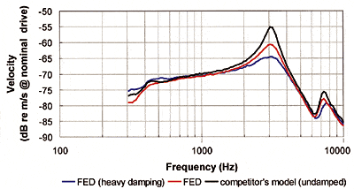
Figure 5. Vibration output for receivers with and without
ferrofluid. Velocity of the cover near the tube is expressed in
terms of dB relative to 1 m/s at nominal voltage drive (ie, 102.5
dB re SPL output at 1 kHz at nominal drive).
Conclusions
The results of this study indicate that ferrofluid receivers provide screenless damping with major benefits to the end-user of hearing instruments, including: 1) Improved shock protection versus standard receivers (>50% improvement); 2) Reduced vibration (and therefore greater gain before feedback); 3) Reduced receiver clogging due to the removal of the damping screen. When combined with an effective cerumen management system, hearing instruments with ferrofluid driven receivers should positively impact consumer satisfaction by providing a higher level of product reliability.
| This article was submitted to HR by Janice LoPresti, PhD, senior engineer, and Sergei Kochkin, PhD, director of market development and market research at Knowles Electronics, Itasca, Ill. Correspondence can be addressed to Janice LoPresti, PhD, Knowles Electronics, 1151 Maplewood Dr., Itasca, IL 60143; email: [email protected]. |
References
1. Kochkin S. MarkeTrak III identifies key factors in determining customer satisfaction. Hear Jour. 1993; 46(8): 39-44.
2. Kochkin S. MarkeTrak VI: Ten year customer satisfaction trends in the U.S. hearing instrument market. Hearing Review. 2002; 9(10): 39-44.
3. Kochkin S. MarkeTrak VI: Consumers rate improvements sought in hearing instruments. Hearing Review. 2002; 9(11):18-22.
4. Kochkin S. MarkeTrak V: Why my hearing aids are in the drawer: The consumer’s perspective. Hear Jour. 2000; 53(2): 34-42.
5. Kochkin S. The effectiveness of a wax protection system in reducing receiver replacements. Hearing Review. 2001; 8(9): 40-41.
6. Kochkin, S. Finally, a solution to the wax problem. Hearing Review. 2002; 9(4): 46-48.


