Are you struggling to explain to clients what those T1 to T4 ratings for cell phone and hearing aid compatibility mean, or how the values are derived? This article is designed to help you understand these issues.
By David Seabury and Brian J. Hill, MS, MBA
The use of wireless devices for both personal and business applications continues to rise exponentially in developed and now in many emerging countries. Mobile phone use now exceeds 2 billion customers worldwide, and the market is rapidly approaching 3 billion. Increased capability is being added everywhere to mobile phones.1
A major shift is also occurring in consumer interest from network carriage to content: End users are moving from a mostly verbal-only mode to the growing array of audiovisual, multimedia, high-impact experience options. Applications and content are industrial megatrends, and mobile technology enablers are driving this phenomenal change. Who would have imagined a few years ago that:
- Mobile phone cameras sold in 2005 would far exceed digital cameras?
- There would be more music/video players in mobile than iPods?
- More messaging via mobile would be possible with a wider reach than PCs?
Is it any wonder that there is such strong influence from the digital TV, radio, music, and entertainment industries on mobile phones? Mobile marketing and mobile business are also booming in applications and interest. Mobile ticketing and transport, machine-to-machine (M2M), and mobile health care have barely scratched the surface of their potential, but they will almost certainly impact all of our lives in ways that we cannot even yet predict.
The US government has taken a strong position that individuals with hearing impairment should have access to the networks through digital wireless phones. The testing and enforcement of wireless devices comes under the auspices of the Federal Communications Commission (FCC).
The US Hearing Aid Compatibility Act of 1988 requires that audio frequency magnetic output of a wireline telephone be compatible with the operation of a hearing aid. This legislation, which has become known as the “HAC Act,” extended FCC requirements to phones intended for use on the public switch telephone network. With the introduction of wireless devices and services in the 1990s, it was determined that excessive RF interference could substantially interfere with the audio signal, but mobile phones were initially exempt from the requirements due to a lack of existing measurement standards.

|
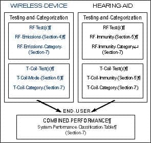
| FIGURE 1. Organization and use of the HAC standard. |
In 2001, ANSI C63.192 was initially approved as the measurement standard with relevant ratings, providing hearing-impaired individuals with access to wireless devices and services. Figure 1 is adapted from ANSI C63.19, and provides an overview of the standard as defined in the main sections of the document. The standard addresses both hearing aids and wireless communications devices (WDs). As such, it applies emissions levels for operational compatibility in WDs, including cordless phones, PCS phones, and VoIP devices that operate in the range of 800 MHz to 3 GHz.
For the hearing aid, susceptibility tests are required for all types that provide an acoustic output. These tests include both RF and the telecoil mode emission measurements for the WD. Correspondingly, the hearing aid is tested for immunity in the microphone and telecoil mode. All test levels are then categorized to provide a combined performance rating of both devices (ie, hearing aid and mobile device). ANSI C63.19 states that:
“…the purpose of this standard is to establish categories for hearing aids and for WDs that can indicate to healthcare practitioners and hearing aid users which hearing aids are compatible with which WDs, and to provide tests that can be used to assess the electromagnetic characteristics of hearing aids and WDs and assign them to these categories.”2
In July 2003, the FCC issued document R7O 03-168, which removed the exemption for WDs from the original HAC Act (ie, WDs were forced to comply), referencing the 2001 ANSI standard. Unlike the FCC-specific absorption rate (SAR) requirements, HAC requirements apply not only to wireless phone manufacturers but also to wireless phone service providers or carriers.
An implementation timetable was established, requiring that by September 2005, service providers offer consumers access to defined percentages of handsets that met the RF or E and H field emissions requirements. The following year, fewer models would need to meet the telecoil categories. By February 2008, service providers must ensure that at least 50% of all handset models available meet the RF emissions levels.
These requirements have a major impact on the complex compliance requirements directed at telecom manufacturers, who already deal with electromagnetic compatibility, SAR, and over-the-air testing. Coupled with ever-shorter design and product life cycles, consumer demands for increased functionality, and extreme price competition, all providers are looking for speed and simplicity in meeting the compliance test requirements.
|
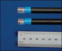
| FIGURE 2. The axial and transverse telecoil probes. |
Hearing aid and hearing aid component manufacturers in general have been quick to react to immunity issues. Most digital hearing aids produced today employ shielding of key components.
Complicating the HAC compliance issue for mobile phone manufacturers and service providers are problems with the 2001 ANSI standard, which became apparent during early WD testing. The standard was republished in 2006 after many revisions, and a significant amendment was immediately added. In October 2006, the FCC took the position that new devices submitted for approval would need to be tested to either the 2005 or 2006 versions of the standard.
Testing and Categorization
The radio frequency measurement requirements for HAC compliance are somewhat similar to SAR test procedures. Both HAC and SAR involve closely coupled near-field measurements over the face of a wireless device, accomplished by moving a precision electromagnetic field probe controlled by a robotic device. In testing for HAC compliance, the measurements are on peak field strength, and are made in air and not through a tissue-simulant fluid as with SAR. HAC compliance testing also requires separate scans in E (electric) and H (magnetic) fields, and the E and H field HAC measurement probes should have an isotropic response and be calibrated in accordance with IEEE 1309.
|
| FIGURE 3. 2-D scan with an E-field probe (wireless device at bottom). |
Measurements on a WD’s telecoil performance are also specified in HAC testing. For this, care must be taken to separate the desired audio-band magnetic signal emanating from the WD from the undesired magnetic interference generated by incidental circulating currents in the WD’s battery or LCD. For these telecoil measurements, two special probes have been designed to respond separately to the axial and to the transverse components of the magnetic signal (Figure 2). The probes, about 10 mm in diameter, contain tiny coils made up of more than 20 meters of ultrafine AWG51 copper wire. The raw signals they detect are amplified and filtered by specialized audio equipment to ensure that the levels are completely unaffected by outside influences.
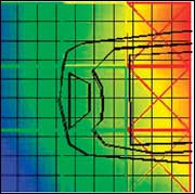
ANSI C63.19 requires the HAC test platform to provide a system validation measurement. In this measurement, E and H field scans are taken along a dipole fed with a known input power and compared against a theoretical value. During actual measurements on a WD, separate robotic scans are made over a 5- x 5-cm grid using an E-field probe, an H-field probe, and the T-coil probes (Figure 3). Each 5- x 5-cm grid must be divided into nine smaller subgrids, with the overall center of the grid lying immediately above the acoustic (or telecoil) output, and at a known distance.
|
| FIGURE 4. Schematic of the 2D scan, showing the 3 rejected subgrids in red. |
Determining categories. In determining an overall category for the WD, the standard allows for three contiguous subgrids around the peak signal to be discarded in the E and the H scans separately. Figure 4 depicts the results of the 2D scan, and the subgrids are outlined in red. In practice, these would correspond to a localized hot spot from the WD, which the hearing aid user could avoid by repositioning the WD slightly against the ear. Unfortunately, the consumer will not see these data. The combined performance category for the WD in the RF band requires that a minimum of five common subgrids in the E and H scans be included with the center subgrid.
The WDs are rated in categories from M1 to M4, with M1 being the worst performance (highest emissions) and M4 being the best. A similar categorization is measured for the WD’s telecoil performance (T1 to T4, by reference).3
|
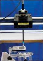
| FIGURE 5. HAC testing system capable of the four axes of required movement. Photo Courtesy of ETS-Lindgren/Index SAR. |
Consumer Use of Data
From published data, a user can assess any likely incompatibility issues simply by adding together the hearing aid’s immunity category with the emissions category of the WD. A total of four or more indicates the combination would be usable—with higher numbers representing even better choices. Conversely, a sum of three or fewer would highlight a problem combination, either because the WD was emitting relatively large signals, or because the hearing aid was particularly susceptible to interference.
One US wireless carrier has described this to consumers as follows:
“Handsets that receive a hearing aid compatibility rating of M3 or M4 have met or surpassed the ANSI hearing aid compatibility standard as adopted by the Federal Communications Commission.
- M3-rating indicates the handset has satisfied the ANSI standard
- M4-rating indicates the handset has exceeded the ANSI standard
|
| FIGURE 6. The M-mode (RF scan) test results |
The higher the M-rating the handset has the lower the Radio Frequency emissions level and higher signal quality the handset will have.”1
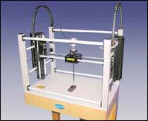
Testing and report generation of a WD for both RF and telecoil modes is relatively straightforward and not overly time consuming, because test platforms are mostly automated. HAC testing can be done in a few hours. Figure 5 shows a typical system capable of the four axes of required movement.
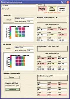
Most HAC test systems also provide automatic reports that capture the required data for reporting to the FCC. Figure 6 shows the output for the RF scans under Section 4 of C63.19, and the telecoil data as specified under Section 6 can be similarly displayed.
One would hope that, with the efforts and costs extended by all involved parties, there also will be be some future qualitative analysis to assess the end results for individuals with hearing impairment so they will enjoy full access to the offerings of mobile wireless devices. The authors take this matter personally, as should HR readers; we are fast approaching entry into the target demographic for hearing aid use, and at the same time we are almost totally dependent on connections to the wireless world.
|
| “Business Decisions: Specifying the Modern Hearing Test Environment,” by Brian Hill, MS, MBA. May 2006 HR.“Hearing Loss and Its Impact on Household Income.” Results of a study conducted by the Better Hearing Institute. October 2005 HR. |
References
- Netsize, Informa Telecoms & Media. Netsize Guide 2006: Small Screens, Global Vision. Paris: Netsize SA; 2006.
- American National Standards Institute (ANSI). American national standard for methods of measurement of compatibility between wireless communications devices and hearing aids (ANSI C63.19). Available at: www.ansi.org. Accessed March 21, 2007.
- FCC Consumer and Government Affairs Bureau. FCC Consumer Facts: Hearing Aid Compatibility for Telephone Equipment. Available at: www.fcc.gov/cgb/consumerfacts/hac.html. Accessed on March 21, 2007.
- Verizon. Hearing aid compatibility. Available at: aboutus.vzw.com/accessibility/digitalPhones.html. Accessed March 19, 2007.
Correspondence can be addressed to HR orand.
About the authors: David Seabury is senior product manager at ETS-Lindgren Electromagnetic Energy Measurement Devices, and Brian J. Hill, MS, MBA, leads the product management at ETS-Lindgren, the parent company of Acoustic Systems, in Cedar Park, Tex. Seabury is active on both IEC62209 and IEEE1528 SAR standard development project teams; Hill has worked as an executive at two hearing instrument manufacturing companies and is active in the fields of acoustics, electromagnetic compatibility, and wireless over-the-air performance measurement testing.