The benefits of hearing instruments with directional microphones are well known.1-3 Traditionally, directional microphone amplification was achieved by using the behind-the-ear (BTE) hearing instrument, a style that is still widely used today. In recent years, however, the technique of building directional amplification in custom instruments like the full-concha in-the-ear (ITE) model has become increasingly popular. Studies suggest that the directional benefit obtained from these custom instruments is equal or superior to that of the BTE style.2,4
While the ability of directional hearing instruments to improve the signal-to-noise ratio (SNR) is well recognized, and provides a direct patient benefit, many patients object to the larger size of the full-concha ITE instrument. In some cases, this results in the patient rejecting directional microphone technology. It is in the manufacturer’s best interest, therefore, to construct a more cosmetically acceptable product that does not sacrifice the excellent directivity that is available in a full-shell model. Indirectly, it also is in the patient’s best interest, as hopefully this will encourage more patients to use directional microphone products.
Because space on the faceplate of half-shell (HS) hearing instruments is limited, and a conventional directional microphone requires a relatively large volume, few directional HS models that include a traditional volume control are currently available on the market. The following article provides background on the design, engineering and electroacoutical considerations encountered relative to the development of the Siemens HS VoiceMic.
Cartridge Development
The initial goal was to create a high-performance, low-cost directional microphone for half-shell hearing instruments with a standard volume control that meets the same design goals as the VoiceMic full-shell ITE.3 The overall objective was to produce a small HS instrument with a high AI-DI (articulation index-weighted directivity index) that offered low-noise circuitry and high sensitivity, and also featured ease of assembly and repair.

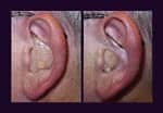
The new directional HS had to be small enough to be cosmetically acceptable for people with normal ear size (Fig. 1) and had to allow for the creation of a more compact directional HS faceplate. In order to minimize the dimensions of the new microphone cartridge, the front and rear spouts found on the full-shell ITE VoiceMic were removed and the rear acoustic screen was placed inside the directional cartridge case (Figs. 2a-b).

Further space was saved by creating a microphone assembly comprised of a directional cartridge and a modified omni-directional dual-microphone cartridge with internal suppression of the resonance peak (damping). The two cartridges are assembled in a way that places the front inlets of the directional and omni-directional cartridges in close proximity to each other, creating an opportunity for optimization of the faceplate design. The directional microphone is designed to provide a hyper-cardioid directional pattern for the receiving port spacing of 6.5 mm. These “combo” cartridges were developed by Knowles Electronics. Both cartridges have identical electroacoustic performance and fit well into the shape of either the right or left canal hearing instrument.
The directional and omni-directional microphones that comprise each cartridge have closely matched sensitivities. As a result, when the user switches between directional and omni-directional modes, there is no significant change in loudness. The drawback resulting from the HS combo cartridge’s compact design is that, in case of receiver failure, both cartridges must be replaced as an assembly, which raises the cost of repair. On the other hand, this design guarantees that the volume balance of the assembly is always maintained, even after repair, and the geometry of the combo cartridges allows for easy assembly.
Faceplate Development
The faceplate design was crucial for achieving the half-shell hearing instrument’s design goals such as: minimizing the footprint (size) for the microphone, achieving the best possible acoustic performance, simplifying the assembly procedure and providing an attractive appearance for the hearing instruments.
Because increasing the distance between the receiver ports improves sensitivity and performance in noise5, it is beneficial for the faceplate design to maximize the distance between the ports. At the same time, the dimensions of the faceplate must remain as small as possible for cosmetic reasons and to allow the hearing instrument to be fit on people who have small ears. The VoiceMic construction minimizes the space occupied by the microphone on the faceplate and creates a separation distance between the front and rear ports of the HS faceplate, which is larger than the microphone cartridge, improving its performance (Fig. 2b).
The design used to address this issue is quite similar to that of the full-concha ITE VoiceMic faceplate4, where the microphone is partially recessed into the faceplate, and special acoustic channels are molded into the body of the faceplate. These channels link the front receiving port to the front inlets of the directional and omni-directional cartridges, while the rear receiving faceplate port is connected to the rear inlet of the directional cartridge via a similar, but independent channel. This compact construction technique saves space on the surface of the faceplate by allowing the front receiving port to feed both microphone cartridges, so only two receiving ports are required (as opposed to the ITE faceplate design, which required a separate port for each microphone). The two windscreens are intended to reduce the wind noise, make the faceplate more cosmetically appealing and protect the microphones from foreign particles (Fig. 2b).
Compared to a conventional omni-directional microphone, the HS VoiceMic takes little extra space on the faceplate. The resulting two-microphone combo with a standard volume control has a fitting rate (e.g., the percentage of people whose ears will physically accommodate the instrument) that is almost as good as that of the conventional HS faceplate with its single microphone and volume control.
Electroacoustical Performance
Although cosmetics played a substantial role in defining the HS hearing instrument design parameters, a more important criterion was the maintenance of the same directivity index as offered by the full-shell model. Through the elimination of spouts on the directional cartridge and the use of short channels to link the microphone inlets with the receiving ports, it was possible to achieve an improvement in DI for the half-shell model of 0.8 dB at 5000 Hz compared with the full-shell model (Fig. 3).

|
| Fig. 3. Directivity Index (DI) of the full-shell versus the half-shell ITE instruments. |

|
| Fig. 4. Typical polar pattern of the half-shell ITE instrument. |
The typical polar pattern response of the directional portion of the half-shell model is shown in Fig. 4. The polar response at 500 Hz, 1000 Hz and 2000 Hz is close to the theoretical limit for a first-order directional microphone: a hypercardioid shape with well-defined notches. Fig. 5 shows DI data for the hearing instrument measured using the KEMAR.
Both ITE and HS hearing aids are measured by deriving polar responses at different frequencies, using the KEMAR, which is rotated in horizontal plane. The DI is then calculated and AI-DI is produced by multiplying DI values by “band-importance” weightings to assign more weight to the directional advantages for the frequencies most important for speech intelligibility. The test data shows the AI-DI for the HS model to be 4.8 dB, which is slightly less than the AI-DI of the full-shell model (Fig. 6).

|
| Fig. 5. Directivity index of the HS instrument fitted on KEMAR (anechoic chamber, single plain measurements). |

|
| Fig. 6. The HS versus full-shell ITE directivity index and AI-DI on KEMAR (anechoic chamber, single plain measurements). |
Considering the above facts, the question naturally arises, “If the DI of the half-shell instrument when measured without using the KEMAR is higher than the DI of the full-shell instrument (Fig. 3), why does the DI of the half-shell instrument, when measured on the KEMAR, appear to be less than the DI of the full-shell model?” The answer lies in the difference in the locations of the receiving ports of the full-shell and half-shell aids, once placed in the ear.

|
| Fig. 7. Typical position of the full-shell ITE (l) and half-shell (r) models in the KEMAR ear. |
This can be illustrated by drawing an imaginary line through the centers of the receiving port of the ITE (or HS) hearing instrument and call it the ITE (or HS) reference line. If we insert a directional hearing instrument into the right ear of the KEMAR and position it in the test chamber (according to ANSI S3-35-85), the ITE reference line will be directed towards the test loudspeaker (Fig. 7). Since the HS hearing instrument sits deeper in the ear than a typical ITE hearing aid, its reference line is tilted farther away from the KEMAR reference line than the ITE reference line. This difference in the tilt angles of the ITE and the HS directional hearing instruments accounts for a significant part of the variance in AI-DI values of HS and full-shell ITE directional aids.
This article addressed design issues inherent in the development of the HS VoiceMic hearing instrument. The new system was developed to provide a good fitting rate and use with or without volume controls. Additionally, the product was designed to deliver an AI-DI that is similar to the full-shell model, while maintaining a cosmetically appealing and ergonomically efficient design. Behavioral research with this product has revealed improved speech understanding in noise consistent with the AI-DI findings.6
This article was submitted to HR by Oleg Saltykov, MS, who is a senior electro-acoustic engineer at Siemens Hearing Instruments, Inc. Correspondence can be addressed to HR or Oleg Saltykov, MS, Siemens Hearing Instruments, Inc., 10 Constitution Ave. Piscataway, NJ 08854-6155; email: [email protected].
References
1. Mueller HG & Wesselkamp M: Ten commonly asked questions about directional microphone fittings. In S Kochkin & KE Strom’s (eds) High Performance Hearing Solutions, V.3, Suppl to Hearing Review 1999; 6: 26-30.
2. Ricketts TA & Mueller HG: Making sense of directional microphone hearing aids. Amer Jour Audiol 1999;8(2):117-127.
3. Mueller HG & Ricketts TA: Directional microphone hearing aids: An update. Hear Jour 2000; 53: 5, 10-17.
4. Hernandez A, Saltykov O, Doudoukjian G & Lin M: A directional-plus-omni system: An improved design for directional hearing aids. Hear Jour 2000; 53: 10, 54-57.
5. Thompson S: Dual microphones or directional-plus-omni: Which Is Best? In S Kochkin & KE Strom’s (eds) High Performance Hearing Solutions, V.3, Suppl to Hearing Review 1999; 6: 1.
6. Velde TM & Saltykov O: New directional two-mic technology for custom hearing instruments. Presentation at the Amer Acad Audiol annual convention, Chicago, March 2000.