The standard of professional practice for verification of the accuracy of a hearing aid fitting is to measure the acoustic signal generated by the hearing aid in the patient’s ear canal. Yet, for a variety of reasons, hearing professionals have been reluctant to use this proven technology.
This article introduces Integrated Real-Ear Measurement (REM), a real-ear measurement system that is completely integrated into Starkey’s Destiny 1600 line of hearing instruments. Since Integrated REM is part of the hearing aid itself, it takes up no extra space in fitting rooms and avoids the expense of external real-ear equipment. Furthermore, the test procedure takes less than a minute of the practitioner’s time. For the first time, the power of digital processing offers a means of gaining this important information for every patient accurately, quickly, easily, and economically.
Clinical Use of Real-Ear Measurements
In the early 1980s, probe microphone calibration procedures—which had long been standard equipment in the auditory physiology laboratory—were applied to measuring the acoustic response of hearing aids in the human ear. Today, commercial devices for this purpose have been available for about 20 years. Recognizing its importance in the accurate fitting of hearing aids, the American Academy of Audiology (AAA) has identified REM as the standard of practice for verifying hearing aid fittings.1
The essential role of REM is to objectively quantify the acoustic output of a hearing aid in a patient’s ear canal. While a variety of approaches to REM are used, the essence of the procedure is to place a probe microphone in the ear canal to measure the sound pressure level (SPL), or gain, provided by the hearing aid. It is an objective, more accurate, and more meaningful alternative to measurement of functional gain.
In spite of the acknowledged importance of REM in hearing aid fitting, its use in the professional dispensing community is surprisingly low. The 2006 HR Dispenser Survey2 showed that, although more than half (57%) of dispensing offices possess REM equipment, only about one quarter (23%) use it routinely during adult hearing aid fittings. Similarly, Table 1 shows the results of a Hearing Journal poll of audiologists and hearing instrument professionals regarding their use of REM.3

|
| TABLE 1. Results of a survey by Kirkwood3 asking nearly 500 hearing professionals how often they perform real-ear (probe microphone) measurements. Entries in the table show the percent of responses in each category. |
Why is REM not used more extensively? Informal conversations with practitioners suggest several reasons for low usage, including the high cost of equipment, space demands in typically small offices, and the time needed to perform the testing. Some object to the cumbersomeness of REM equipment, which usually includes a computerized control and display module, a speaker mounted on a flexible boom, and probe and reference microphones attached to the patient’s head by a headband or hook over the ear.
Practical considerations aside, one might ask how important REM really is to the task of fitting and fine-tuning hearing instruments. Every hearing professional adjusts hearing aids based on informal patient reports, and some make further adjustments based on formal behavioral measures. The informal queries generally revolve around questions of clarity, loudness, sharpness, comfort, and the sound quality of other voices and the patient’s own voice. Parameters are adjusted to address these and other subjective concerns.
However, even though skilled adjustments based on behavioral observation are essential, the best starting point is knowledge of the signal reaching the patient’s eardrum.1,4-7 Without that basic information, fine-tuning adjustments are really a combination of practitioner experience, guesswork, and luck.
Even the most experienced practitioner cannot know the acoustics of a given ear canal without objective measurements. The answer to the question, “How does that sound, Ms. Jones?” simply does not contain sufficient information to direct all fitting adjustments accurately.
Conventional Real-Ear Measurements
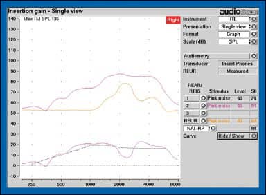
The basics. A basic understanding of several quantities will help us understand real-ear measurements. They include real-ear aided response (REAR), real-ear unaided response (REUR), and real-ear insertion gain (REIG). These quantities are illustrated in Figure 1, and their official definitions from the ANSI Standard for Real-Ear Measurements4 are reported in the sidebar on page 46. An additional important quantity, real-ear coupler difference (RECD), will be used as an accurate and convenient means of deriving real-ear data.
REAR and REIG offer different ways to quantify the amplified signal in a patient’s ear canal. REAR is defined as the output of the hearing aid in dB SPL at a point inside the canal close to the eardrum in response to a known signal outside the ear canal.
|
| FIGURE 1. Example of basic real-ear measurements from an Audioscan Verifit system, showing REAR (upper pink curve), REUR (yellow curve), and REIG (lower pink curve) fitted to a prescriptive target (broken black line). |
REIG is the difference between REAR, the SPL in the ear canal with a hearing aid in place and turned on, and REUR, the SPL at the same point in the ear canal with no hearing aid in place. REUR shows the gain created by the resonance characteristics of the ear canal. REIG thus accounts for the fact that the net effect of the hearing aid is the difference between the unaided gain of the ear canal itself and the aided gain provided by the hearing aid after the canal effect is taken away.
The RECD alternative. The measurements above, defined in the ANSI Standard for Real-Ear Measurements,4 all require that a probe tube be in place in the ear canal for the duration of the measurements. An alternative approach uses RECD to adjust the hearing aid response to a patient’s amplification requirements without having the probe tube in the ear while acoustic adjustments are being made.8-12
The first step in the RECD approach is to measure the response of the hearing aid in a standard 2cc coupler. The one great virtue of a 2cc coupler is stability; with care the same acoustic response can be measured repeatedly with little variation.
Couplers, however, do a rather poor job of representing the acoustic performance of a hearing aid once it is placed in a patient’s ear. The second step in the RECD approach is to measure the REAR with the same hearing aid at the same settings in the patient’s ear canal. The difference between these two measurements is the real-ear coupler difference (RECD), or…
RECD = REAR – Coupler response
If we can determine the RECD for an ear, we can then use that information along with knowledge of the coupler response to derive the REAR for a hearing aid in that ear. That is…
REAR = Coupler response + RECD
At this juncture, the coupler response can be adjusted as needed (to match a target or make adjustments) and becomes the foundation for extrapolating the hearing aid response to the real ear.
An alternative to using the hearing aid itself to derive RECD is to generate a known signal from an insert receiver and measure its output in a coupler and in the ear.12,13 The difference between these two quantities yields the RECD, which can then be used to predict a hearing aid’s real-ear response from its coupler response. Once measured, the RECD can be applied to any response in the coupler to predict the corresponding real-ear response.
The RECD approach is popular in pediatric hearing aid fittings because of the challenge of keeping a young child quiet and stationary for the extended time required to perform conventional real-ear testing. The RECD determination requires keeping the child still only long enough to do one quick measurement with a probe tube in the ear. Once that measurement is done, the aid can be fitted to a real-ear target in the 2cc coupler and then placed in the child’s ear.
Simulated Real-Ear Measurements
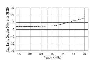
Hearing aid manufacturers typically use average RECDs in their programming software and from them derive aided responses that are, in fact, simulations of real-ear responses. An example of an average RECD (Figure 2) shows that the difference between coupler and real-ear response increases with frequency.
|
| FIGURE 2. Example of average RECD as a function of frequency in an average adult ear canal. (Replotted from Sachs and Burkhard.17) |
While average RECDs offer a reasonable starting point for fittings, some practitioners assume incorrectly that they represent actual behavior of a specific hearing aid in a specific patient’s ear. In reality, the average RECD is only a simulation or prediction, and its accuracy will depend on how close each individual ear is to the average.14,15 (For a summary, see the November 2005 HR article “The Accuracy and Clinical Usefulness of Manufacturer-Predicted Values in Adult Hearing Aid Fittings,” by Nancy Aarts, PhD, and Carrie Caffee, MS.) Adhering too closely to an average RECD and the resulting average real-ear response may result in significant error in fitting a hearing aid to a prescriptive target.
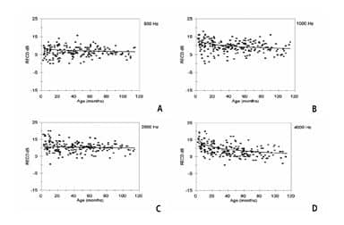
RECDs vary considerably from one ear to another,13,16,17 as seen in Figure 3. The proximity of an individual patient’s RECD to the average RECD will determine the accuracy of the fit to target for each patient. If the patient happens to have an RECD close to the average, then the fit to target will be quite appropriate. If, however, the patient’s RECD is higher than the average, such that the actual SPL generated in the ear is higher than expected, then fitting to the average target will create too high an output level in the ear, with the risk of excessive loudness. Conversely, if the patient’s RECD is lower than average, then fitting to the average target will result in the patient being underamplified. Either type of error is likely to reduce benefit and mandate more visits to the hearing professional for adjustments.
|
| FIGURE 3. RECDs from 392 infants and children ages 1 month to 16 years, illustrating wide variability.13 |
REMs Without External Equipment: Integrated Real-Ear Measurement
Destiny 1600 hearing aids use the power of modern digital processing to perform calibrated real-ear measurements without the need for external equipment. All Destiny 1600 hearing aids, from BTE to CIC models, are equipped to work with Starkey’s Inspire OS programming software to measure individual real-ear responses. This revolutionary development allows practitioners to take advantage of REM accuracy without the expenditure of time, space, and money required in the past. The technique relies on two direct acoustic measures, plus an accurate model of the complex behavior of the hearing aid when its response parameters are adjusted.
Individual coupler response. Before any Destiny 1600 instrument leaves Starkey Laboratories after manufacture, its coupler response is measured, and the resulting data are stored digitally in the hearing aid. It is noteworthy that these data are not mere averages for this circuit and model, but are specific to this very instrument, thus taking into account any variability in sensitivity inherent in individual transducers.
|
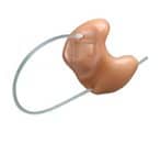
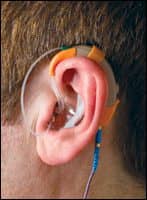
| FIGURE 4. Destiny 1600 custom ITE instrument, showing probe tube attached to microphone port and extending through vent. |
|
| FIGURE 5. Destiny 1600 BTE with probe tube attached to specialized ear hook and passing through vent into patient’s ear canal. The orange band behind the earhook covers the rear port of the directional microphone during calibration. |
Individual real-ear response. At the time of the fitting, the output of the hearing aid is calibrated once again, this time yielding an REAR in the patient’s ear canal. To do this, the Inspire OS software puts the hearing aid into a special calibration mode, in which the hearing aid microphone and receiver perform tasks quite different from their usual ones. The receiver temporarily becomes a calibrated signal source, and the microphone becomes a probe microphone, picking up sound from inside the ear canal rather than the outside environment. In other words, these two transducers become the essential components of a real-ear measurement system.
These two data sets—the coupler response of each individual hearing aid and the REAR of each ear with the hearing aid in place—are critical to this integrated real-ear approach. Destiny 1600 is the first hearing aid to carry these data on board the hearing aid.
Each Destiny 1600 has a thin probe tube, with one end inserted into the ear and the other attached to the hearing aid microphone (Figures 4 and 5). During the fitting, the HA generates a calibration signal in the ear, that is picked up by the probe tube and measured by the hearing aid microphone. The 2cc coupler response of the aid is subtracted from this real-ear measurement to yield a measured, not simulated, RECD.
Instructions on the Inspire OS fitting screen tell the practitioner how to position the probe tube in a patient’s ear canal, using the intertragal notch or canal aperture as a landmark, either through the vent or alongside the shell or earmold. Because insertion depth of the probe is critical to achieving an accurate RECD,8 the probe tube is marked to assist in proper placement, beginning 10 mm from the medial end, with additional marks every 5 mm up to 25 mm.
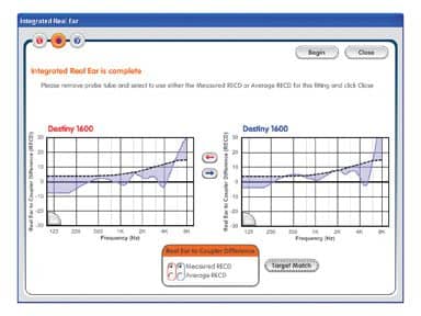
After positioning probe tubes in both ears, the practitioner starts the calibration procedure, and the broadband calibration signal is presented to each ear, in rapid succession, for about 4 seconds each. The software displays the measured and average RECDs (Figure 6) and offers the option of accepting the measurement or reverting back to the average RECD. The measured RECDs in this example differ considerably from the average RECD. Note also that these RECDs show the expected high degree of symmetry between the left and right ears.18 A warning message will appear if the probe tube appears to be blocked, preventing a valid measurement.
|
| FIGURE 6. Inspire OS software screen that appears after running Integrated REM, showing the average and measured RECDs. |
Advantages of Integrated REM Over Conventional RECDs
The RECD capability of the Destiny 1600 gives more information than the typical RECD technique performed with conventional REM equipment. The conventional approach, used at the time of the fitting, allows a hearing professional to adjust an initial hearing aid response in the coupler to improve the match to a patient’s real-ear targets. While this is a good starting point, further adjustments to the aid cannot be monitored in real time, when the aid is in the patient’s ear.
In contrast, the Destiny 1600 Integrated REM accurately models the real-ear response in real time as response parameters are adjusted. This capability arises from having an accurate and complete model of the gain and output behavior of all channels and all bands of the hearing aid. When a parameter is changed in the programming software, the exact effect of the change is seen in the real-ear graph on the Inspire OS screen. And, unlike conventional REM procedures, a probe tube does not need to be in the ear at the time.
Great care has been taken in the Inspire OS to portray accurate coupler and real-ear responses. The hearing aid modeling used by the software tracks gain and output for two types of input—long-term average speech spectrum and tones—while also taking into account the detailed effects of compression ratios, compression thresholds, and maximum outputs, across eight channels and 12 bands. The resulting detailed coupler responses, when combined with measured RECDS, provide a precise representation of hearing aid behavior in the real ear.
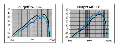
Research is under way to compare the REARs on the Inspire OS software screen with REARs measured with conventional REM equipment. As an example, the black line in each graph of Figure 7 represents the REAG displayed on the Inspire OS software screen after fitting to target using the average RECD values. If a patient has an RECD equal to this average, it will produce this output. The turquoise curve represents the Inspire OS REAG when the measured RECD is used. Subject SG has an RECD lower than the average, meaning that in her ear the hearing aid generates a lower SPL than average. Subject ML shows just the opposite, an RECD higher than average, creating a correspondingly higher SPL.
|
| FIGURE 7. Real-ear aided gain in two subjects. Black line: REMs on Inspire software screen, when aid was fitted to target based on average RECD. Turquoise line: REMs on Inspire software screen, when aids were fitted to target based on measured RECD. Blue line: REMs measured with a commercially available real-ear system. |
The question, then, is whether the modeled REAGs using measured RECDs agree with conventional probe microphone measures of the programmed responses. The REAGs of these subjects measured with conventional REM equipment (Audioscan Verifit) are shown as blue curves in Figure 7. In both cases the responses measured with conventional equipment agree with the responses generated by Inspire OS using the measured RECDs.
In the case of patient SG, reliance on the average RECD would have resulted in a response as much as 10 dB below target for that ear because the programming software would have incorrectly assumed that the output in this ear was higher than it actually was. In contrast, the RECD measured by the Integrated REM and Inspire OS software yielded an REAR virtually identical to that measured with the commercial real-ear system.
Patient ML shows an error in the opposite direction. In this case, reliance on the average RECD would have resulted in a response that exceeds the actual target by as much as 10 dB. Once again the Integrated REM with a measured RECD yields a response very similar to the response measured with a commercial system.
Using Integrated REM To Map Live Voice
Integrated REM provides more than just an accurate fit to a prescriptive target. With the first release of Starkey’s Inspire OS in April 2006, a new tool called SoundView was introduced, which is a real-time graphic representation of the simulated output of a patient’s hearing aids in response to a live input. Now, SoundView incorporates Integrated REM to provide a more accurate real-time display of real-ear output.
With hearing aids in a patient’s ears, SoundView displays the output of the aid in response to any acoustic input, a spouse’s voice, music, or whatever one might wish to use. It allows the professional and the patient to view input to the aid alone, output alone, or input and output simultaneously.
|
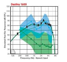
| FIGURE 8. Examples of SoundView input and output displays for a Destiny 1600 ITE. The input was long-term average speech-shaped noise with an overall level of 70 dB SPL generated by the Fonix FP35 real-ear analyzer. |
To assess the accuracy of the new SoundView feature, a calibrated signal—speech-spectrum noise at an overall level of 70 dB SPL—was presented to a subject’s Destiny 1600 hearing aid. Figure 8 shows three representations of that signal in SoundView. The lower green line represents the noise input to the hearing aid and the blue line the output of the hearing aid, as measured by SoundView. The shaded regions around the two SoundView curves show the range of outputs over a 10-second time window. The bold green line with black markers represents the expected output of the aid as modeled by Inspire OS. The fact that the output measured by SoundView is very close to the output modeled in Inspire OS attests to the accuracy of the model.
Summary
Integrated REM represents an exciting new possibility in real-ear measurement. With Integrated REM in Starkey’s Destiny 1600 hearing aids, hearing professionals will be able to perform accurate real-ear testing as an intrinsic part of the fitting protocol.
Benefits of Integrated REM include:
- What you see is what you get (WYSIWYG): Integrated REM takes the guesswork out of hearing aid fittings.
- More accurate initial fit to prescriptive targets, reducing the chances of overfitting or underfitting, and increasing confidence in fitting accuracy.
- Accurate monitoring of hearing aid performance after the initial fitting to guide ongoing adjustments.
- A built-in real-time monitor of the hearing aid input and output with SoundView, to illustrate to practitioner, patients, and families exactly how the hearing aids are responding to a live input.
- A tool that builds patient confidence in your skills and the technology you are using, enhances patient counseling, and differentiates your practice as a provider of high-end products and services.
- A tool that truly supports evidence-based practice, which has become the guiding principle in the fitting of hearing aids.

|
| More on verification The only way to be certain a hearing aid is performing correctly is to measure it yourself, says Sridhar Krishnamurti, PhD, in his article “Measuring Performance: A Defining Professional Responsibility” in the January 2006 HR. |
To top off the list of benefits, integrated REM will require less than a minute of additional time, no additional equipment, and no more space than the hearing aid itself. For the first time, hearing professionals and patients will be able to reap the known benefits of real-ear testing without the challenges that have kept so many from adopting this tool.
Acknowledgments
The authors are grateful to their colleagues Joyce Rosenthal and Laura Woodworth for their helpful suggestions in the creation of this article.
References
- Valente M, Abrams H, Benson D, et al. Guidelines for the audiological management of adult hearing impairment. Audiol Today. 2006;18:5.
- Strom KE. The HR 2006 dispenser survey. Hearing Review. 2006;13(6):34.
- Kirkwood D. Survey: Dispensers fitted more hearing aids in 2005 at higher prices. Hear J. 2006;59(4):48.
- American National Standards Institute (ANSI). American National Standard Methods of Measurement of Real-Ear Performance Characteristics of Hearing Aids (ANSI S3.46). New York: Acoustical Society of America;1998.
- Dillon H. Hearing Aids. Thieme: NewYork; 2001.
- Dillon H, Keidser G. Is probe-mic measurement of HA gain-frequency response best practice? Hear J. 2003; 56(10): 28-30.
- Tecca J. In: Valente M, ed. Use of real-ear measurements to verify hearing aid fittings. Strategies for Selecting and Verifying Hearing Aid Fittings. New York: Thieme;1994: 88-107.
- Ching TYC, Britton L, Dillon H, Agung K. NAL-NL, RECD, & REAG: accurate and practical methods for fitting non-linear hearing aids to infants and children. Hearing Review. 2002;9(8):12-20,52.
- Fikret-Pasa S, Revit L. Individualized correction factors in the pre-selection of hearing aids. J Speech Hear Res. 1992;35:384-400.
- Moodie KS, Seewald RC, Sinclair ST. Procedure for predicting real-ear hearing aid performance in young children. Am J Audiol. 1994;3(1):23-31
- Seewald RC, Moodie KS, Sinclair ST, Scollie S. Predictive validity for a procedure for paediatric hearing instrument fitting. Am J Audiol. 1999;8(2):143-152.
- Zelisko D, Seewald R, Gagne JP. Signal delivery/real ear measurement system for hearing aid selection and fitting. Ear Hear. 1992;13:460-463.
- Bagatto MP, Scollie SD, Seewald RC, Moodie KS, Hoover BM. Real-ear-to-coupler difference (RECD) predictions as a function of age for two coupling procedures. J Am Acad Audiol. 2002;13(8):407-415.
- Hawkins DB, Cook JA. Hearing aid software predictive gain values: how accurate are they? Hear J. 2003;56(7):26-34.
- Aarts NL, Caffee CS. Manufacturer predicted and measured REAR values in adult hearing aid fitting: accuracy and clinical usefulness. Int J Audiol. 2005;44:293-301.
- Fabry D. Nonlinear hearing aids and verification of fitting targets. Trends Amplif. 2003;7(3):99-115.
- Sachs RM, Burkhard MD. Earphone pressure response in ears and couplers. Paper presented at: 83rd Meeting of the Acoustical Society of America; April 21, 1972.
- Munro K, Buttfield L. Comparison of real-ear to coupler difference values in the right and left ear of adults using three earmold configuations. Ear Hear. 2005;26(3):290-298.