By Francis Kuk, PhD
The key to a successful fitting is verification. Fittings involving frequency lowering algorithms are no exception. Here’s how to verify them.
One of the key factors in a successful hearing aid fitting is that the dispensers verify the fittings.1 Indeed, Kochkin showed that dispensers who verified and validated their fittings had 1.2 fewer patient visits than those who did not. Unfortunately, fewer than 35% of dispensers performed these tasks routinely.
Kochkin’s data did not specifically address hearing aids that use frequency lowering (FL) technology. It is speculated that clinicians who fit such technology are less able to verify their fittings with certainty than those who fit conventional technology. This is because there is not a standard way to verify the performance of a FL device. Using the linear frequency transposition algorithm (called the Audibility Extender or AE) in the Widex Clear hearing aids as an example, this paper discusses how FL may be verified, and recommends a simple tool to verify the AE.
Why Is It Important to Verify a FL Fitting?
Variations in implementation among manufacturers. Even though FL technology has been around since the 1970s, there is not a general consensus on how best to apply this technology. For example, the two most common approaches to frequency lowering—linear frequency transposition and frequency compression—differ substantially from each other. In the former case, high frequencies above a start frequency are transposed to a lower frequency area.2 In frequency compression, the higher frequencies are compressed to the lower, adjacent frequencies.3 Furthermore, how much of the high frequency sounds need to be transposed or compressed is not generally agreed upon. Some may desire FL to add audibility above 4000-6000 Hz only, while others may default for a broader range of frequencies to be lowered.
Some hearing losses are so severe that even with frequency lowering there is no audibility of the lowered sounds. The default settings can only be viewed as a tentative starting point and not the end-point of the fitting.
Diverse wearer needs. While it is conventional to fit a hearing aid for optimal speech understanding, a hearing aid wearer may have other hearing requirements for their devices as well. For example, a bird watcher may like to hear bird chirps at 8000 Hz, a frequency region where most hearing aids fail to amplify or amplify with limitations. A mechanic may need to hear a specific high frequency engine noise to diagnose machine problems. In these cases, the need for the AE will most likely be appreciated by the wearers in those specific listening situations. Using the default settings without verifying with the relevant stimuli may fail to convince the wearer of the usefulness of such an algorithm.
Initial reactions may not be predictive of eventual performance. Frequency lowering transforms high frequency sounds into lower frequency sounds. This results in an “unnatural” sound percept that initially may be objectionable to some patients—even if FL is beneficial. Unfortunately, many dispensing professionals facing this type of complaint will immediately reduce the amount of frequency lowering so that it sounds less unnatural. Some choose a less aggressive degree of FL as the default to avoid confronting the wearers about the potential initial negative reaction.
But a wearer’s reaction is frequently based on past experiences and not by what will be experienced in the future. For example, et al4 have shown that many people with a severe-to-profound loss who previously wore linear hearing aids reported insufficient loudness when they were initially fit with nonlinear hearing aids. However, the same listeners accepted the nonlinear hearing aids and demonstrated improved performance over time. Kuk et al5 also showed that, despite the initial unnatural sound percept, the average adult wearers of the AE algorithm accepted the algorithm in about 2 to 4 weeks. Interestingly, children were less likely to report negative reaction to the use of frequency transposition.6
This suggests that the initial subjective impression is not a reliable predictor of the eventual acceptance or the ultimate benefit of FL. Indeed, using the criterion of immediate acceptance without verification could fall short of providing wearers with the necessary high frequency information.
It is necessary that clinicians have the basis to insist wearers should continue to use frequency lowering despite the potential of initial unnaturalness. Verification is the tool that ensures benefits of the recommended lowered settings.
So, What Needs To Be Verified in a Frequency Lowering Algorithm?
The nature of frequency lowering. The purpose of any amplification device is to provide audibility. Thus, a logical objective in verifying the output of a FL algorithm is to examine the improvement in audibility. This improvement takes at least two forms: through stimulation of the existing frequency regions and through redistribution of information to the remaining frequency regions:
Addition. Improvement through addition allows information carried by the high frequency fibers to be heard as high frequencies. This “adds” to the frequency range that is heard. The use of traditional amplification, such as linear and nonlinear amplification, is an example of improvement through addition.
Redistribution. Improvement through redistribution allows information carried by the high frequencies to be redistributed so that other frequency regions carry the information instead. In FL, information from the high frequency is redistributed to the lower frequency areas. The idea is to retain the high frequency information even though it may sound different. As in all cases of redistribution, information carried by the existing frequency regions will need to be restructured to accommodate the new spectral information (which was previously inaudible and cannot be made audible simply by amplification).

|

|
| Figures 1a-b. Spectrogram of the word /spot/ processed by linear (master) amplification and (a) linear frequency transposition and (b) frequency compression starting at 2000 Hz and a CR of 4:1. |
The redistribution takes two forms in frequency lowering. Frequency transposition takes the high frequency information and moves it to the lower frequency. For example, Figure 1a shows the spectrogram of the word /spot/ measured through a frequency transposition algorithm for someone with normal hearing up to 2500 Hz and then a profound loss (>90 dB HL) beyond 3000 Hz. On the left is the spectrogram measured with the “master” program, and on the right is the frequency transposed program. Note that the region above 3000 Hz is transposed down to the region between 1500 Hz and 3000 Hz. This makes the /s/, which typically has a spectrum above 4000 Hz, sound like /sh/ because of this spectral change. Also note that the transposed /s/ and /t/ sounds do not mix with the original sounds below the 3000 Hz cutoff frequency because there is no energy below 3000 Hz when the /s/ and /t/ sounds are produced. However, the higher-order formants of the vowel /o/, after transposition, may mix with the lower formants. Because the lower-order formants are typically more intense than the higher-order ones, any impact from this masking is minimal.
In frequency compression, higher frequencies are compressed into the lower frequencies. In the process, the lower frequencies carry the information from the higher frequencies. Figure 1b shows that one can compress the frequencies above 4000 Hz to below 4000 Hz using a cutoff frequency of 2000 Hz and a compression ratio (CR) of 4:1. In this process, the /s/ sound will again sound like the
/sh/. The higher-order formants also will be compressed and become less distinguishable from the lower-order ones. One may have a higher cutoff frequency and/or a lower CR; however, the lowered high frequencies may not be audible with the profound loss above 3000 Hz. Thus, all forms of frequency lowering result in varying degrees of artifacts the impact of which depends on the hearing loss of the wearer and the relative intensities and target locations of the lowered sounds in reference to the original sounds.
Thus, a consideration in all frequency lowering algorithms is to achieve audibility while minimizing the occurrence of any artifacts (such as confusion and masking). If they are unavoidable, one needs to consider if they could interfere with real-world speech understanding and devise a means to minimize the impact. If the impact can be overcome in real life, then the focus of the fitting (and verification) should be on ensuring audibility.
On the other hand, if the impact of these artifacts cannot be overcome, then an additional requirement in verification of FL devices should include an examination of these potential redistribution artifacts. The current model of verification may not be sufficient for a FL algorithm.
Impact of Learning and Acclimatization
Despite the potential of redistribution artifacts and laboratory tests confirming them using nonsense syllables, few claims of confusion were reported in real-world situations. For example, Kuk et al7 showed that frequency lowering resulted in confusion among consonants on a nonsense syllable test. However, the same authors also showed that such confusion decreased over time (within 2 months) with use of the AE. Meanwhile, word confusion was not reported with real-world use of the AE.
The discrepancy between laboratory test and real-world use is probably facilitated by two mechanisms. First, these participants also underwent a training exercise over a 1-month period. The effect of training, along with the right acoustic cues, helped them acclimate to the new acoustics and make sense of the redistributed cues.8,9 Second, in the real world, hearing-impaired listeners also use visual cues for speech understanding. The phonemes that were reportedly most confused with the AE were visually the most distinct from each other (eg, /s/ vs /sh/).10 This may have helped the subjects adjust to the differences in acoustic cues.
These studies have implications on how one should face potential initial confusion. If the approach is that the initial confusion should be avoided at all costs, the resulting fitting may not be optimal in the long run. On the other hand, if one looks beyond the initial confusion and continues the use of FL, a higher level of performance over time may be achieved. Our findings lead us to believe that, as long as the audibility of the desirable sounds is achieved, much of the potential initial confusion can be resolved over time via training/experience with the algorithm.
Criteria for Verification
Evidence suggests the criterion of objective audibility is still the most critical aspect in verifying a FL algorithm. However, it is desirable that the verification procedure include considerations that can enhance our understanding of what is being verified.
Specifically, the verification procedure should consider:
1) Is FL needed (over a traditional non-FL program)?
2) Does it confirm audibility of the unreachable high frequency?
a) For general speech understanding such as the /s/ sound?
b) For specific listening needs (eg, bird chirps)?
3) Does it show which frequency regions are impacted by the transposition; which frequency channels are transposed (or compressed); and to which frequency regions are they transposed (or compressed)? This could provide insights on potential spectral confusion and/or masking.
How Is Frequency Lowering Verified?
Aided soundfield thresholds. The aided soundfield threshold reflects the softest level of sound that can be heard by the wearer of a nonlinear hearing aid,11 with or without frequency lowering. The use of aided soundfield thresholds as a verification index for FL has been reported.6,12 One should be reminded that the thresholds of the lowered high frequency sounds are not mediated by the high frequency fibers, but rather from lower frequency fibers to which the high frequency sounds are lowered (compressed or transposed). Thus, if thresholds in the lower frequency are poor to begin with (and insufficient gain is provided or a low compression ratio is used), the aided thresholds of the lowered high frequency will remain poor. The aided thresholds do not reflect any of the redistribution artifacts that were previously discussed because no mixing of sounds is evaluated during its measurements.
Aided soundfield thresholds are typically measured using warble-tones. This measurement has been criticized for its variability and limited reliability.13 Thus, it is desirable that this index can be predicted without measurement. Such is the case if in-situ thresholds are measured and utilized in the fitting procedure. Kuk et al14 showed that the aided soundfield thresholds measured in a controlled environment were within 3 dB of the predicted aided thresholds when in-situ thresholds were measured. This suggests that these thresholds can be used efficiently to estimate audibility without the typical problems associated with aided soundfield threshold measures.
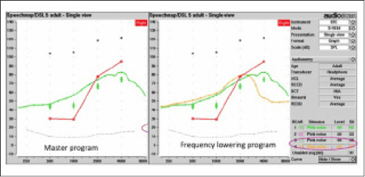
REM. Real-ear measurement (REM) has been advocated as the “best practice” to verify the performance of hearing aids. Typically, a standard broadband stimulus (such as speech-shaped noise or ISTS signal) is presented to the hearing aid worn in-situ. With the conventional program (ie, no lowering), the hearing aid output will show a significant portion of the amplified spectrum below the patient’s thresholds (Figure 2a). With FL (and depending on the parameter settings), many will continue to show no output in the high frequencies beyond the start frequency (Figure 2b, yellow curve). There may be a slight “bump” in the mid-frequency region where sounds are transposed.
|
| Figures 2a-b. Outcome of real ear-measurement using standard broadband stimulus for (a) conventional hearing aid, and (b) frequency lowering hearing aid with a start frequency at 2500 Hz. |
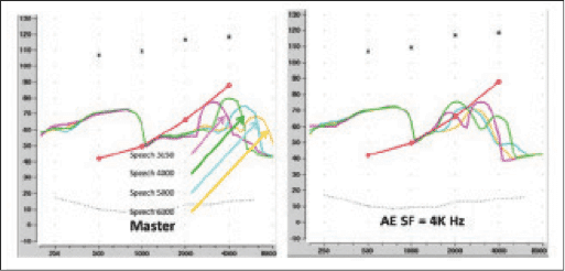
Thus, the information provided by a conventional REM system in verifying FL is limited because of the available stimulus options. Recently, the Audioscan Verifit REM system has made available a special stimulus to improve the ease of detecting a lowered sound. The speech-shaped stimulus is modified by attenuating 30 dB above 1000 Hz, except for an isolated 1/3-octave band centered at the frequency indicated by the name of the stimulus (Speech3150, Speech4000, Speech5000, Speech6300).15 During verification, the clinician chooses one of the stimuli, presents it with the hearing aid in the non-AE mode (ie, master program), and notes that the peak frequency is still below the in-situ threshold of the wearer (Figure 3a). Then, the same stimulus is repeated with the AE program (Figure 3b). In an optimal fitting, the AE program will move the peak frequency from the sub-threshold level to above threshold at a lower frequency. Verification is ascertaining that the transposed sound is above the patient’s in-situ threshold in the lower frequencies. Otherwise, adjustment can be made on the AE parameters to achieve audibility. This approach has the advantage of easily verifying that the transposed sound is indeed audible. Because of the availability of four stimulus options, one may choose different stimuli to evaluate the wearer.
|
| Figures 3a-b. Audioscan Verifit REM output showing the use of the Speech stimuli (a) without transposition and (b) with transposition AE start frequency at 4000 Hz. |
The choice of stimuli (Speech3150 vs Speech6300) deserves some deliberations. Clearly, the choice should be driven by the need of the wearer to hear a specific frequency. That is, if the wearer cannot hear sounds above 4000 Hz under conventional amplification, then the stimulus that should be used is the Speech4000 Hz (and higher) stimulus. If this stimulus is not audible under the current FL settings, then the settings need adjustment to make Speech4000 audible. The use of another speech stimulus (eg, Speech3150) would not be informative.
Using the speech stimulus for verification has the same limitations as aided thresholds in that any mixing of the original and lowered sounds, or displacement of the original sounds, is not visible. Thus, only audibility of the once-inaudible high frequency sounds is evaluated using REM/Verifit.
Cortical Auditory Evoked Potentials (CAEP). Another objective verification approach that shows future promise is the recording of cortical responses to speech stimuli such as
/ma/, /ga/, /ta/, and/or /sa/ (to represent stimuli in low, mid, and high frequency regions). This can be especially useful in the case of pediatric fitting or cases where the determination of behavioral thresholds is difficult.16
In this approach, the wearer is prepared for evoked potential measures (such as electrodes on the scalp). When evaluating the FL algorithm, the test stimuli are presented to the Master and the FL programs. If the FL program is necessary and set appropriately, one observes a response with the FL program but not with the Master program when the high frequency stimulus (ie, /ta/, or /sa/) is used. The FL program lowers the high frequency sounds into a lower frequency region, thus enabling the cortical responses in the lower frequencies. If no response is observed with the FL program, the FL parameters are adjusted until a cortical response is present.
Using CAEP has the advantage of objectively ensuring that the acoustic stimuli have reached the cortex. CAEP differs from other verification tests, such as REM where the level of assessment is peripheral. A limitation of CAEP is that, for some individuals, a cortical response is only present at a relatively high sensation level.17 This may make it difficult to conclude that the lack of response is due to inappropriate AE settings. Other issues, such as how the nonlinearity of the hearing aid processor may affect the outcome, also need to be resolved. Furthermore, any mixing of the lowered and original sounds is not examined by this technique. It’s likely that more evaluation of this technique will be undertaken in the future.
New Options: Verifying Audibility and More
The verification tool for the FL algorithm should not only show the increase in audibility of the high frequency sounds, but also identify the location of where the source sound is lowered. This information provides clinicians with the needed data to make an informed decision on the appropriateness of the fitting (and selected parameters), and to further adjust them should they not be optimal. The SoundTracker in the Widex fitting software provides such capability when it is used to verify the FL algorithm (ie, AE) accurately and efficiently.
A detailed description of the SoundTracker (ST) has been published,18 as well as a description on how to use the ST to fit/select the optimal start frequency in the AE.19 The remainder of this article elaborates on how the ST is designed to integrate all the considerations when verifying the AE feature in the Widex Clear hearing aids.
|
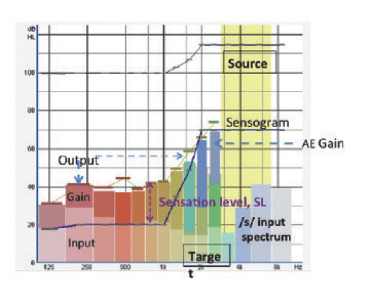
| Figure 4. Example of the SoundTracker screen showing the Audibility Extender (AE) fitting. |
Figure 4 is a screen display of the ST when used in verifying the AE feature. The key ingredients that make the ST a valuable verification tool are:
Measured input and simulated in-situ output. Briefly, the ST measures the effective input at the hearing aid microphone in each of the 15 channels and displays the simulated real-ear output at the eardrum using the proprietary Widex prescriptive formula. Each channel is color coded for ease of identification. The lighter colored bars represent the input level at each channel, while the gain at that channel is represented by the darker colored bar. The overall instantaneous output is represented by the height of the colored bar. In this way, the clinician knows exactly the intensity of the input signal in each channel, as well as its instantaneous output.
Illustration of AE operation. When it is used to verify the AE, the source region (frequency to be transposed) will be highlighted in yellow (see Figure 4, from 3200 Hz to 6000 Hz). The frequency region to which the transposed high frequency sounds are moved is called the target region. It is identified by an overlap of the gain bars from the source region (light green and blue bars) on the gain bars one octave from the source region (greenish and brown bars, from 1600 Hz to 2500 Hz). Thus, the ST conveniently shows that the start frequency is at 3200 Hz; the sounds that will be moved are from 3200 Hz to 6000 Hz (green and blue channels), and the frequency regions that receive the transposed sounds are from 1600 Hz to 2500 Hz (brown and green channels). This information provides the clinicians an objective assessment of the appropriateness of the fit.
Indication of audibility. In addition, the in-situ threshold (or sensogram, dark blue line) is displayed on the same graph. Because both the sensogram and the output of the hearing aid are measured on the same 711 coupler, the sensation level—or the dB difference between threshold and output shown on the SoundTracker—is identical to the SL shown on a real-ear measure (REM) under the same stimulus condition. Thus, the information on the audibility of a particular sound is identical to that provided through REM. This makes it convenient to verify if the output of a hearing aid is audible without the use of additional external devices.20
For example, Figure 4 shows that the sensogram at 1000 Hz is 20 dB HL. One also notes an instantaneous output of 42 dB HL. Thus, Figure 4 shows a SL of 22 dB, indicating that the sound is audible even without transposition. One can see that, at 6000 Hz, the input is at 40 dB HL. Because there is “no gain” being applied at that frequency (because it is being transposed) and the bar is below the sensogram, 6000 Hz is not audible as a 6000 Hz. However, if we look at the grayish dark blue bar (which was used to represent gain at 6000 Hz before), it is now shown on top of the 2500 Hz gain bar with an instantaneous output of 75 dB HL. Since this is above the sensogram (of 70 dB HL) at 2500 Hz, the wearer would hear the 6000 Hz signal as a 2500 Hz sound with a SL of 5 dB.
Figure 4 also shows if the transposition results in any potential masking of the original signal. Masking occurs when the transposed sounds have the same frequency as the original sound and both occur at the same time. However, if one looks at Figure 4, at the moment when the 3200-6000 Hz is transposed to 1600-2500 Hz, the input at 1600-2500 Hz is less than 20 dB HL (which is the noise floor of the room). Thus, the transposed sounds do not overlap with any original sounds (since there is none in this case). The transposed sounds (or darker color bars) have to be higher in level than the original amplified sound to result in significant masking or word confusion. Thus, the ST provides not only information on the audibility of a sound, but also information on potential masking, if such occurs.

|
| Figure 5. Comparison in output display between the Audioscan Verifit and the SoundTracker. |
Proven accuracy and validity. We compared the output displayed on the ST to that displayed on the Audioscan Verifit system using the same Speech stimuli (eg, Speech4000) available from Verifit. Figure 5 shows the display on the Verifit (left) and the ST (right) with the Master (top) and the AE (bottom) programs. On the Verifit, one can see the AE transposes the average peak at 4000 Hz (which is inaudible with the Master program) to a 2000 Hz region above the in situ threshold. On the ST using an averaging function, one sees the upper range of the input (in shaded green) for the 4000 Hz signal is still below the sensogram (inaudible). However, with the AE, the peak is now moved to 2000 Hz, suggesting that the transposed 4000 Hz is now heard as a 2000 Hz. Note that both the ST and the Verifit show the peak at the identical frequency region; however, the Verifit shows the average output and the ST shows the range of the output (ie, both the upper and lower limit of the output range).
Verification Procedure to Ensure Audibility with Minimal Artifacts
The stimulus. One may use the /s/ phoneme presented between 30 and 40 dB HL as the stimulus. This stimulus is available on the Compass fitting software (LifeSounds). The spectrum of the signal as displayed on the SoundTracker is shown in Figure 6. An input level between 30 and 40 dB HL is advocated since this is the lower limit of /s/ when it is produced at a conversational level. In this case, it is equivalent to around 50-60 dB SPL overall. One can simply examine the input level on the ST to make sure the appropriate input level is used.
|
| Figure 6. Acoustic spectrum of the /s/ phonemes as displayed on the SoundTracker in dB HL and dB SPL units. |
If the AE is used for the purpose of hearing specific sounds (eg, birds chirping), it is desirable to have a recording of the sound and use that as the stimulus instead. Because the actual level of the desirable sound may be different from the recorded level, additional adjustment of the gain parameter may be necessary after real-life use of the AE program.
The criterion. Because one of the issues in verifying FL is to avoid unnecessary lowering, verification of the AE should proceed only after verifying that the Master program (without AE) does not provide audibility of the /s/ sound (or desirable sound).
To determine audibility, one should make sure that the amplified /s/ (shown above 4000 Hz, represented by the blue bars in Figure 7) is above the sensogram. Audibility is demonstrated when any one of the blue bars is above the sensogram. If so, AE is not necessary (Figure 7a). If none of the frequencies within the amplified /s/ spectrum is above the sensogram, AE may be desirable (Figure 7b).
The highest start frequency (least lowering) that achieves audibility of the /s/ should be used. One may first verify that the default start frequency provides audibility of the /s/ sound. If the patient cannot perceive the /s/ sound consistently despite the use of the AE (Figure 7c), the AE parameters (either default or adjusted) would need readjustment (Figure 7d). In the last example, the AE gain was increased so that all the frequencies within the /s/ sound (above 4000 Hz) were audible from 1600 Hz to 2500 Hz.
The ST provides immediate visual acknowledgement of the audibility of any sounds. When used to verify the AE, it also provides information on whether there is the need for the AE, what frequency regions are transposed, to where they are transposed, and if such transposition provides optimal audibility with minimal confusion and masking. With this information, the clinician can be more certain of the fitting and counsel the patients on appropriate expectations. This promotes higher patient satisfaction and fewer patient returns.
|
Francis Kuk, PhD, is vice president of clinical research at Widex USA and executive director of the Widex Office of Research in Clinical Amplification (ORCA-USA) in Lisle, Ill. CORRESPONDENCE can be addressed to Dr Kuk at: [email protected] |
References
1. Kochkin S. MarkeTrak VIII: Reducing patient visits through verification & validation. Hearing Review. 2011;18(6):10-12.
2. Kuk F, Korhonen P, Peeters H, Keenan D, Jessen A, Andersen H. Linear frequency transposition: Extending the audibility of high frequency information. Hearing Review. 2006;13(10): 42-48.
3. Glista D, Scollie S, Bagatto M, Seewald R, Parsa V, Johnson A. Evaluation of nonlinear frequency compression: Clinical outcomes. Int J Audiol. 2009;48(1):1-13.
4. Kuk F, Potts L, Valente M, Lee L, Picirrili J. Evidence of acclimatization in persons with severe-to-profound hearing loss. J Am Acad Audiol. 2003;14(2):84-99.
5. Kuk F, Peeters H, Keenan D, Lau C. Use of frequency transposition in thin-tube, open-ear fittings. Hear Jour. 2007;60(4):59-63.
6. Auriemmo J, Kuk F, Lau C, et al. Effect of linear frequency transposition on speech recognition and production in school-age children. J Am Acad Audiol. 2009;20(5):289-305.
7. Kuk F, Keenan D, Korhonen P, Lau C. Efficacy of linear frequency transposition on consonant identification in quiet and in noise. J Am Acad Audiol. 2009;20(8):465-479.
8. Kuk F, Keenan D, Peeters H, Lau C, Crose B. Critical factors in ensuring efficacy of frequency transposition II: facilitating initial adjustment. Hearing Review. 2007;14(4):90-96.
9. Kuk F, Keenan D. Frequency transposition: training is only half the story. Hearing Review. 2010;17(11):38-46.
10. Korhonen P. Phoneme error patterns in frequency transposition when using speechreading. Poster presented at: annual American Academy of Audiology AudiologyNow convention; April 6-9, 2011; Chicago.
11. Kuk F, Ludvigsen C. Reconsidering the concept of the aided threshold for nonlinear hearing aids. Trends Amplif. 2003;7(3):77-97.
12. Simpson A. Frequency-lowering devices for managing high-frequency hearing loss: a review. Trends Amplif. 2009;13(2):87-106.
13. Humes L, Kirn E. The reliability of functional gain. J Speech Hear Disord. 1990;55(2):193-197.
14. Kuk F, Ludvigsen C, Sonne M, Voss T. Using in situ thresholds to predict aided sound-field thresholds. Hearing Review. 2003;10(5):46-50.
15. Audioscan RS500SL User’s Guide, version 3. Dorchester, Ontario: Audioscan; 2012. Available at: http://www.audioscan.com/resources/usersguides/Currentslguide.pdf
16. Golding M, Pearce W, Seymour J, Cooper A, Ching T, Dillon H. The relationship between obligatory cortical auditory evoked potentials (CAEPs) and functional measures in young infants. J Am Acad Audiol. 2007;18(2):117-125.
17. Dillon H. Hearing Aids. Sydney, Australia: Boomerang Press, Thieme; 2012.
18. Kuk F, Damsgaard A, Bulow M, Ludvigsen C. Using digital hearing aids to visualize real-life effects of signal processing. Hear Jour. 2004;57(4):40-49.
19. Kuk F, Keenan D, Peeters H, Korhonen P, Hau O, Andersen H. Critical factors in ensuring efficacy of frequency transposition, Part 1: Individualizing the start frequency. Hearing Review. 2007;14(3):60-67.
20. Kuk F. In situ thresholds for hearing aid fitting. Hearing Review. 2012;19(11):26-29.


