Tech Topic/October 2013 HR
How to Verify Wireless Technology
By Peter Kossek and Charlotte T. Jespersen, MA
A review of the main ways in which wireless hearing aid technology is used, and practical tips for verifying wireless features.
Hearing care professionals who have been in practice long enough probably recall when hearing instruments with varying compression schemes became commonplace. Many questions arose regarding how to prescribe gain and output, and how to verify fittings using real-ear or test-box equipment. Established practices and equipment capabilities at the time did not adequately capture how hearing instruments would amplify speech at different levels or how to interpret test results. Eventually, peer-reviewed prescriptions emerged, and clinical test equipment caught up with verification needs. As new hearing instrument features have appeared, instrumentation has been updated to provide tools for evaluating and understanding new technologies.
Today, digital wireless features have become standard fare in hearing instruments at many technology levels, and we find ourselves in a similar situation regarding verification. Hearing aid features based on wireless technologies can form an important part of the product being fit, but it may be unclear how to document or test the functionality. In addition to verification of individual hearing instrument fittings, techniques for verification also can be applied to assist in understanding technologies. If the hearing care professional has a good grasp of what particular technologies actually do to the sound, it is easier to select appropriate candidates for them, explain to patients how they will benefit, and evaluate and choose from among many similar-seeming products and features in the marketplace.
In this article, we will review the main ways in which digital wireless technology is used in hearing instruments, and provide ideas and practical tips for verification or learning about these different features.
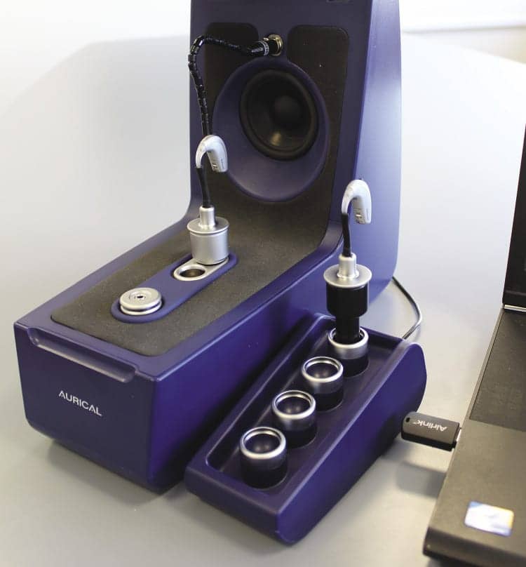
The AURICAL HIT and OTOsuite software from Otometrics are used in the examples in this article. The AURICAL HIT is a test chamber that facilitates measurement of hearing instruments and wireless accessories. An advantage of the AURICAL HIT is the OnePosition Method. Who hasn’t tried mounting a receiver-in-the-ear (RIE) device on a coupler, only to find the receiver wire had caused it to “jump” out of position once the lid was closed, thereby invalidating the measurements? OnePosition alleviates these kinds of frustrating positioning issues and improves the accuracy and quality of results. The integrated coupler and microphone are connected in a designated slot that ensures a correct height relative to signal presentation for any style of instrument and for any measurement. A gooseneck reference microphone allows for easy and secure positioning.
Finally, an external coupler module connects via USB to the AURICAL HIT, allowing for a dual device setup. This lets one hearing instrument or device receive the stimulus while the processed signal is picked up from a second hearing instrument or device. The dual device setup is particularly interesting for evaluating digital wireless capabilities in hearing instruments and accessories.
Basic Digital Wireless Features
The most basic of digital wireless features were also the first ones to be introduced in hearing instruments. These are the transmission of command signals, either from a remote control device to the hearing instruments, or between two bilaterally fit hearing instruments. The purpose of this type of feature is to provide a convenient way for the user or even a third party to operate the hearing instruments. Functionality includes increasing or decreasing volume, and changing listening programs.
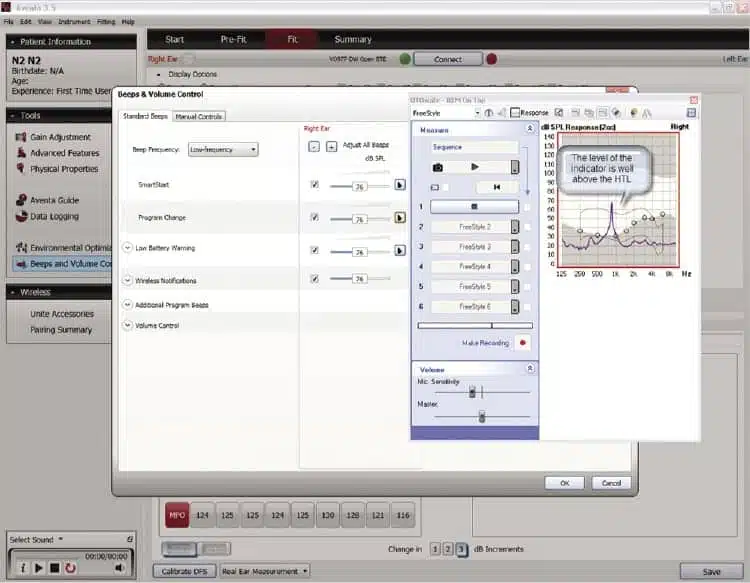
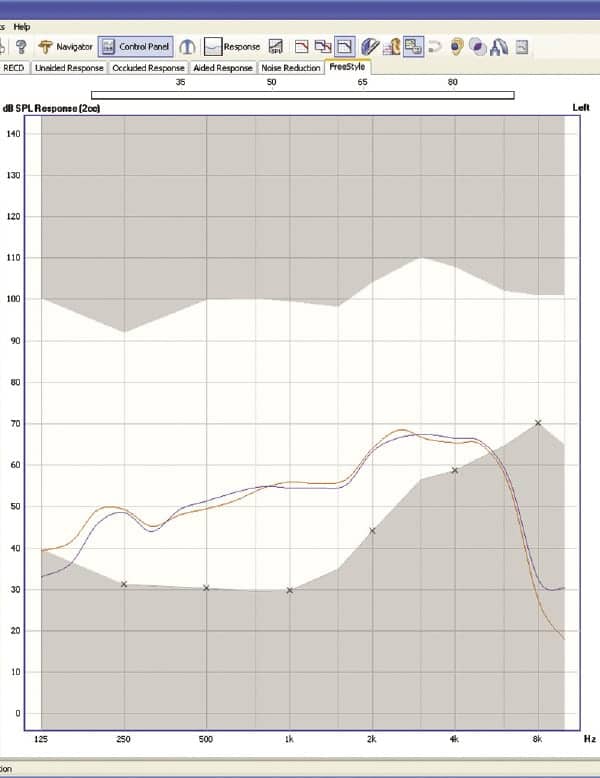
Verification of this type of wireless functionality is simple and requires no special equipment. Just press the buttons and listen to the hearing instruments to ensure that the expected action occurs. However, there may be questions related to what happens when the remote control or inter-device functionality is used. The most obvious is that it may be of interest to compare responses in different programs, or to check the level at different volume control settings. Existing protocols for real-ear or coupler-based verification can be used for this. There might also be questions regarding acoustic indicators that occur with remote control or inter-device command signals that can be investigated with testbox or real ear equipment. For example, the level of acoustic indicators can be checked relative to hearing thresholds using either of these tools. Figure 1 shows how the level of the hearing instrument program change indicator was checked using the Freestyle mode of the Otometrics OTOsuite software with AURICAL HIT.
As the name implies, the Freestyle mode allows the user to freely configure the measurement conditions. For this simple measurement, we mounted a ReSound Verso BTE hearing instrument on the 2cc coupler of the AURICAL HIT. Rather than using the remote control to present the program change indicator, we connected wirelessly to the hearing instrument with the ReSound Airlink so that we could present and, if necessary, change the level of the indicator from the fitting software. The wireless connectivity was also convenient, as it was not necessary to take cable connections into account. We used the “On-Top” view in the OTOsuite to position the measurement window next to the “Beeps & Volume Control” screen in the ReSound Aventa software, such that we could measure the acoustic indicators as we presented the beeps and made adjustments. The Freestyle mode was configured to use “Live” as the recording mode, which means that the output of the hearing instrument is recorded without any stimulus presentation from the speakers in the testbox.
|
| Figure 1. The frequency and level of the ”Program change” acoustic indicator for a ReSound Verso hearing instrument were measured in the AURICAL HIT using the OTOsuite Freestyle mode. This type of measurement could also have been done in the real ear. |
From the measurement in Figure 1, it is evident that the default level for this particular patient was just above 750 Hz in frequency, and was approximately 35 dB above threshold—well below the UCL. In this case, it appears that the default setting is a good starting point that should provide audibility at a comfortable level. While many patients can provide verbal feedback regarding acoustic indicator levels, there might be some who are unreliable reporters where this type of measurement could be worthwhile.
Other Inter-device Features
Sound processing algorithms. Hearing instruments may also use data exchange between devices to steer signal processing algorithms. “Steering” refers to algorithms that control how sound processing is applied. For example, digital noise reduction is a signal processing algorithm that attempts to improve listening comfort by decreasing gain in frequency regions with a poor signal-to-noise ratio.
ReSound NoiseTracker II is an example of a digital noise reduction algorithm. A steering algorithm can then apply the sound processing algorithm in defined ways according to certain criteria. ReSound Environmental Optimizer II can be set to steer the level of NoiseTracker II according to the acoustic environment. The ReSound Verso hearing instrument also uses wireless 2.4 GHz inter-device communication for steering. So in addition to steering the level of NoiseTracker II per the acoustic environment, the Binaural Environmental Optimizer II also aligns the NoiseTracker II settings between the two hearing instruments to prevent distracting imbalances in the sound.
Binaural Directionality. Another steering algorithm of the ReSound Verso that depends on inter-device wireless communication is Binaural Directionality. This feature steers the microphone mode for each device depending on the presence and location of speech and noise in the environment. The benefit of Binaural Directionality is improved signal-to-noise ratio (SNR) while keeping sounds in the aided listener’s environment audible.
Binaural Directionality switches among four different microphone setups, which are listed below. The selected microphone setup will be most beneficial for the current acoustic environment. The four possible microphone settings and their application are derived from external research regarding the optimal microphone responses of two hearing instruments in different sound environments.1-7
• Omni (right device) – Omni (left device)
• Omni (right device) – Directional (left device)
• Omni (left device) – Directional (right device)
• Directional (right device) – Directional (left device)
Microphone response transitions between omnidirectional and directional processing occur gradually, over 10-20 seconds. This allows for a seamless listening experience, which prevents switching due to instantaneous sound events in the environment, as well as perceptual changes in sound quality.
Like other hearing instrument features relying on bilateral exchange of information, it is not readily apparent to the fitter what the hearing instrument is actually doing at any given time. Nor is there typically any evidence that the feature (as advertised) is working at all. In fact, it was a design goal of Binaural Directionality that the switching among microphone modes not be apparent to the user. It was the intention that the user should experience seamless benefit without the feature calling attention to itself per se.
But this does not mean that Binaural Directionality or other algorithms that use inter-device communication in a sophisticated way cannot be observed by means of verification measures. As an added benefit of verifying the functionality of such wireless features, the resulting in-depth understanding may enable clinicians to better counsel patients on how to use the feature and what to expect.
Verifying Binaural Directionality
Although Binaural Directionality is supported with explanatory illustrations that describe the microphone modes that would be activated in different situations, there is no substitute for actually observing the switching of microphone modes in response to different stimuli. This helps to verify that:
1) Inter-device communication and coordinated switching of microphone modes actually does occur, and
2) Stimuli are correctly recognized and classified by the system.
Altogether this helps solidify understanding and instills confidence in the feature.
One way to examine how Binaural Directionality works uses a stimulus presented from behind the hearing instrument to demonstrate switching between omnidirectional and directional responses. Sound coming from behind the instrument will be amplified less if the hearing instrument is in directional mode compared to when it is in omnidirectional mode.
|
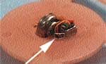
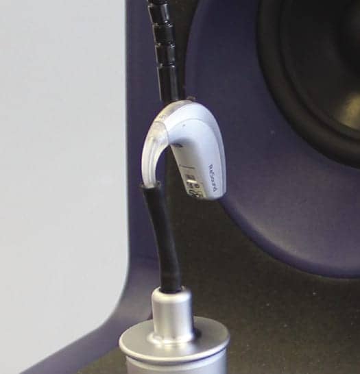
| Figure 2. Setup for verifying binaural directionality. |
For this example, ReSound Verso 977 BTE devices were programmed to the default settings for a symmetric moderate hearing loss. For a symmetric loss, the right hearing instrument will be set to a directional response any time an asymmetric mode is selected, unless speech is detected on the right side and not the left. To isolate the effects of Binaural Directionality, other special signal processing algorithms are disabled in the “Advanced Features” screen, including DFS Ultra II, Auto DFS, Expansion, and NoiseTracker II. To make the directional switching as obvious as possible, the Directional Mix setting can be set to “High.” To perform the measurement:
1) Open OTOsuite and select the User Test named “Binaural Directionality” (can be quickly accessed by pressing F8).
2) Attach the right hearing aid to the coupler in the AURICAL HIT test chamber.
3) Orient the hearing instrument so that the instrument is facing away from the main speaker (see Figures 2 and 3).
|
| Figure 3. Hearing instrument orientation. |
4) At this point, if your test environment is fairly quiet, both hearing instruments will be in omnidirectional.
5) Start the measurement by clicking the “Play” button in the OTOsuite control panel. This will present a Pink Noise signal at 65 dB SPL inside the test chamber.
6) Click the “Immediate” button right after starting the measurement to get a baseline response. This curve represents omnidirectionality. So if the microphone switches, you will see the curve move down.
7) Hold the second hearing instrument close to the test chamber and speak at conversational level for approximately 30 seconds.
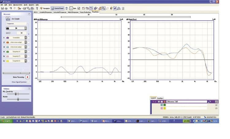
8) After approximately 20 seconds, you should see the gain curve decreasing. Click the “After Voice Adapt” button to capture this response. Figure 4 shows what you might see.
Why does the hearing instrument go to a directional response at this point? It is because the environment identified on the left side (outside the testbox) contains speech, while the environment inside the testbox contains no speech. To ensure audibility of the speech while also increasing noise from behind, the left instrument will remain in an omnidirectional response while the right one will switch to directionality.
|
| Figure 4. Measurement results. The blue curve in the graph on the right shows the gain for the signal coming from behind the instrument when it has an omnidirectional response (baseline). The orange curve shows the response when the hearing instrument has switched to directional. The graph on the left shows the difference curve. Note that the difference is fairly modest, as the directional algorithm for this device is optimized for performance on the head, while these measurements were done with the device mounted on a coupler. |
You can experiment with variations on this test by presenting other signals. For example, if a speech signal is presented both in the testbox and outside the testbox, both hearing instruments will remain in omnidirectional.
1) To observe that the right instrument switches back to an omnidirectional response, present a noise signal to the hearing instrument outside the testbox. This can be as simple as making a “hissing” sound yourself, although it might be more convenient to play a sound file with white noise or pink noise from an external source, such as a smartphone. You will see that the measurement curve returns to the initial baseline level.
2) Click the “After Noise Adapt” button.
3) Click the “Stop” button.
ReSound Verso also features the following inter-device features: Environmental Optimizer II, Synchronized Softswitching, Comfort Phone, Synchronized Push-button, and volume control. All of these features can be verified using the AURICAL HIT.
Verification of Wireless Accessories
|
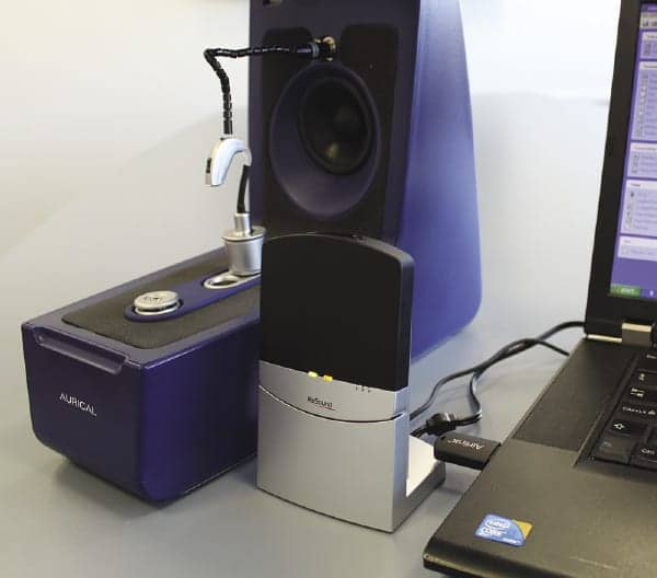
| Figure 5. Setup to verify wireless accessories. |
Most digital wireless hearing instrument systems include accessories that enable the user to stream sound from an external source to the hearing instruments. Depending on the particular wireless technology used in the system, the user may be required to wear a streaming device in addition to having an adaptor that connects to the audio source. The ReSound 2.4 GHz system uses radio frequency (RF) for wireless transmission. RF technology allows “far field” wireless communication, so no body-worn streamer is necessary.
Regardless of the technology, it is possible to verify the “transparency” of the wireless accessory. The idea of verifying transparency and protocols for doing so are already established in connection with FM technology. Briefly, a transparency measurement verifies that the level of the signal coming from the wireless accessory is comparable to the signal picked up by the hearing instrument microphone. In other words, the hearing instrument and the hearing instrument coupled to the wireless accessory would provide the same output characteristics when presented with the same stimulus.
The ReSound Unite™ TV Streamer is an example of a wireless accessory that can be connected to the TV, stereo, laptop, or other sound source in order to link the sound source to the hearing instruments. It is possible to carry out a transparency measurement on this type, as well as other wireless accessories (see Haastrup and Dworsack8 for a review of measuring transparency and SNR advantage with the ReSound Mini Microphone).
The verification procedure is carried out in two steps. In Step 1, the hearing instrument response is measured using an International Speech Test Signal (ISTS) at an acoustical input of 65 dB SPL; in Step 2, the hearing instrument is receiving ISTS from the streamer. Any differences between the two measurements can be minimized by adjusting the level on the streamer or in the programming of the hearing instrument in the fitting software. As in previous examples, we used ReSound Verso 977 BTE hearing instruments for this test. The hearing instruments were fit to a moderate hearing loss, and the same settings were used in the hearing instrument Program 1 and the streaming program.
|
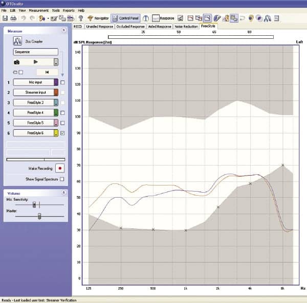
| Figure 6. Before adjustment, the streamed signal shows a slight roll-off in the low frequencies. |
1) STEP 1: Connect the computer line output to the streamer audio input.
2) Navigate to the OTOsuite sound library folder and open the ISTS signal for playback in a standard media player on the PC.
3) All Windows audio settings are set to a signal level comparable to the one of the TV, which usually corresponds to all wave file mixer settings on maximum volume. Remember to restore the original settings after this procedure.
4) Open OTOsuite and select the User Test named Streamer Verification (F8).
5) Mount the hearing instrument on the coupler.
6) Make sure the reference microphone is placed correctly and close the test chamber.
7) Click Button 1 named “Mic input” to start the measurement.
8) When the measurement completes, change the hearing instrument to the streaming program.
9) STEP 2: Start the media player ISTS signal playback.
10) Click Button 2 named “Streamer input” to start the measurement.
11) Stop the measurement after 14 seconds.
12) Compare the curves and make adjustments to streamer volume or hearing instrument programming.
|
| Figure 7. Improvement after adjustment. Low frequency gain for the streaming program was boosted slightly for the streaming program. |
A similar measurement can be done with other wireless accessories, even including mobile phone accessories, such as the ReSound Unite™ Phone Clip+. For a phone accessory, the ISTS signal would be played from a Bluetooth enabled smartphone that is paired with the hearing instruments.
Summary
The functionality of digital wireless technology in hearing instruments does not have to be a mystery. Existing clinical measurement equipment can be used to verify and learn about how wireless features work and whether they meet expectations. This article offered some ideas on how to examine some wireless functionality, but the creative clinician could certainly come up with even more. (Authors’ Note: The user tests for OTOsuite shown in the examples in this paper are available from the authors.)
References
1. Walden B, Surr R, Cord M, Dyrlund O. Predicting hearing aid microphone preference in everyday listening. J Am Acad Audiol. 2004;15:365-96.
2. Walden B, Surr R, Cord M, Grant K, Summers V, Dittberner A. The robustness of hearing aid microphone preferences in everyday environments. J Am Acad Audiol. 2007;18:358-79.
3. Hornsby B. Effects of noise configuration and noise type on binaural benefit with asymmetric directional fittings. Seminar presented at: 155th Meeting of the Acoustical Society of America; June 30-July 4, 2008; Paris, France.
4. Cord MT, Walden BE, Surr RK, Dittberner AB. Field evaluation of an asymmetric directional microphone fitting. J Am Acad Audiol. 2007;18:245-56.
5. Bentler RA, Egge JLM, Tubbs JL, Dittberner AB, Flamme GA. Quantification of directional benefit across different polar response patterns. J Am Acad Audiol. 2004;15:649-59.
6. Hornsby B, Ricketts T. Effects of noise source configuration on directional benefit using symmetric and asymmetric directional hearing aid fittings. Ear Hear. 2007;28:177-86.
7. Coughlin M, Hallenbeck S, Whitmer W, Dittberner A, Bondy J. Directional benefit and signal-of-interest location. Seminar presented at: American Academy of Audiology 20th Annual Convention; 2008; Charlotte, NC.
8. Haastrup A, Dworsack-Dodge M. Electroacoustic evaluation of the ReSound Unite Mini Microphone with Otometrics AURICAL HIT. ReSound white paper, 2012.
CORRESPONDENCE can be addressed to Peter Kossek at: [email protected]
Citation for this article: Kossek P, Jespersen CT. How to verify wireless technology. Hearing Review. 2013;20(11):16-20.
October 2013 HR