Part 2: Practical applications and benefits for dispensing professionals

|
||
| Roy F. Sullivan, PhD, has been practicing audiology for more than 40 years in hospital, university, government, and corporate settings, and he has worked in a private practice since 1973. Dr Sullivan is a partner with his wife, speech-language pathologist Carol A. Sullivan, at Sullivan & Sullivan Inc, Garden City, NY. | ||
Editor’s Note: In Part 1 of this article,1 published in the February HR and available here online, Dr Sullivan shows that the hearing industry has, in less than 6 years, converted from an invest/pour model to a scan/print model for custom hearing instrument shell design and production. The article compares and contrasts the two methods and offers a dispenser’s perspective on why this transformation is important. Part 2 (below) shows how dispensing professionals can benefit from the change.
Dispenser Benefits of Scan/Print Technology
Distinctive features of a successful custom shell design include: ease of insertion, freedom from discomfort during full-time wearing, positional stability (lack of extrusion), and absence of non-vent-related (slit leak) acoustic feedback at in-use gain settings.
Figure 1 lists the major sources of variability in custom shell production. Shell design decisions can be improved by the dispenser’s ability to capture and consistently describe elements of the patient’s otic anatomy, which may be crucial to a successful fit.2
It is less important where the impression scan takes place; it does not matter if it occurs at the dispensing office or at the manufacturer’s factory. What is significant is the critical need for dispensing professionals to share a common understanding of these morphological issues, and the preemptive and remedial actions that are possible using scan/print technology. By adopting impression-taking and processing protocols outlined in this article, the dispenser can identify critical distinctive features in the patient’s ear.
These features may be textually annotated in the non-scanning dispenser’s custom hearing instrument order specification. Dispensers advancing to in-office impression scanning will experience a visually heightened, manipulable, 3-D virtual impression of the patient’s otic void (ear canal). With dispenser-authored, graphically site-specific annotations suggesting virtual modifications to the input.stl image file, the shell designer is provided detailed information. This, in turn, serves as the basis for more consistent, focused design decisions. The benefits of scan/print shell technology may be passively derived or actively enhanced by the dispenser.
Passively Derived Dispensing Benefits of Scan/Print Technology
The following represent benefits that dispensing professionals will receive (and are starting to receive already) due to the scan/print technology being used by manufacturers. Keep in mind that these benefits can be realized by doing little more than what you’re doing now with your impressions:

|
| FIGURE 1. Sources of variability within the ear-to-shell production process path. |
Improved production turnaround time. The digital shell design process is significantly more efficient in instrument turnaround time than the labor-intensive invest/pour process described in the sidebar of Part 1 of this article. The digital SLA shell printing process can run 24/7.
Heightened shell dimensional accuracy and replication. Based on the author’s repeated digital micrometric measurements with two sets of six “clone” CIC shells, preliminary estimates of dimensional variability, intrinsic to the SLA CIC shell production process, were derived. Findings suggest that ≠68% of specified SLA shell dimensions (±1 standard deviation) will fall within ±0.07 mm, and 95% of shells (±2 standard deviations) will fall between ±0.14 mm.
This represents a degree of morphological accuracy heretofore unattainable using the traditional invest/pour shell production processes. In addition to creating proprietary templates that aid in stabilizing the shell design process, individual manufacturing laboratories have also developed tables of scan/print shell design offsets corresponding to the various viscosities of impression materials.
Optimally placed circuit components and transducers. A review of the digital design stages in Part 1 of this article highlights the care and control exercised by the shell designer in efficiently placing circuit components and transducers within the virtual shell.
Improved otic conformity appropriate for the selected morphology. The shell designer has the ability to model a shell’s appearance and fit within the patient’s virtual ear. This enhances the probability of comfort and cosmetic approval by the patient.
Optimum internal thickness. Shells can be manufactured with an optimum internal thickness to facilitate in-office detailing at the time of fitting and follow-up. CIC shells can be printed up to a full millimeter in thickness, with even greater shell density deposited in areas typically requiring detailing.
Exact duplicate or replacement of lost or physically damaged instruments. Replacement custom instruments can essentially be cloned on demand using laboratory-cached output.stl files. Duplicate, lost, and damaged instruments can be replicated exactly with an Internet-based order by simply referencing the original instrument’s serial number. It is no longer necessary for the dispenser to submit a new ear impression or to order, store, and ship polysiloxane investments for each replacement fitting.
Polysiloxane (clear) investments can be requested, based on impression scan files. The full, unedited input.stl is printed and invested. Investments can be used by dispensers for
- Ordering and fabrication of RSAs3 and
- Insertion and removal dexterity training with patients.
|
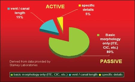
| FIGURE 2. Estimated proportion of custom instrument ear impressions received with and without supplementary dispenser morphological input (courtesy of Starkey Laboratories). |
Actively Derived Dispensing Benefits of Scan/Print Technology
Gudmundsen4 has presented an integrated view of the importance of attention to the morphological features of custom fittings. Estimates provided by Starkey Laboratories, perhaps the world’s largest manufacturer of custom hearing instruments, suggest that only a minority of dispensing professionals specify morphological details in their custom instrument orders (Figure 2). Dispensers advancing to in-office impression scanning will experience a visually heightened, manipulable 3-D virtual impression of the patient’s otic void. With dispenser-authored, graphically site-specific annotations suggesting virtual modifications to the input.stl image file, the shell designer is provided detailed information. This serves as the basis for more consistent, focused, shell-design decisions, leading to more successful custom fittings.
| FIGURE 3. Suggested dispenser protocols for impression-taking and processing. Click here for a larger image (PDF) |
A flow chart (Figure 3) outlines in-office impression-taking procedures for invest/pour and scan/print shell processes using either silicone or ethyl methacrylate impression materials. Unlike silicone impressions, ethyl methacrylate impressions are intrinsically laser-translucent and therefore non-reflective. Custom hearing instrument manufacturers employ a coating to render these impressions opaque and laser scan-reflective. Impression scans can be transmitted to the laboratory within minutes of taking them, avoiding all the longer-term dimensional distortions reported by Agnew5 and other researchers.6-9
The author, in his second year of in-office impression scanning and input/output.stl image processing, has transitioned to a two-part, medium-viscosity, addition-cure polysiloxane impression material6 (Silasoft™ from Microsonic) that is fully laser-reflective, presenting a comparable viscosity or syringe “shoot feel” with a setup time comparable to the familiar Audalin™ material.
By incorporating scan/print technology, in conjunction with video otoscopy, dispensing professionals can direct shell designers’ attention to palpable, dynamic otic features, including hyper-distensible ear canals and TMJ artifacts. This will often eliminate the need for less comfortable, high-density impressions with bite blocks. Pirzanski10-13 has developed a strong case against routine use of low viscosity, cartridge-mixed materials delivered to the ear via mechanically advantaged syringe. This type of delivery system effectively removes critical proprioceptive feedback to the dispenser during the impression-taking process.
|
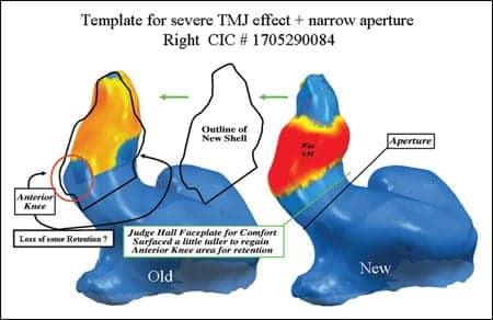
| FIGURE 4. Example of a shell design template for a specific set of otic conditions. (courtesy of Bob Manning, Starkey Laboratories). |
Dispenser Morphological Design Input
Scan advantages without in-office scanning. In-office impression scanning is a natural extension of the hearing industry’s complete migration to the scan/print production model. However, even without scanning, the dispenser can actively provide text-based morphological pre-specifications that the laboratory can incorporate into the digital shell design process.

|
|
• Pirzanski C, Berge B. Is the end near for acoustic feedback? April 2004 Hearing Review Online Archives. • Oliveira R, et al. The dynamic ear canal and its implications. February 2005 Hearing Review Online Archives. • Pirzanski C. Earmolds and hearing aid shells: a tutorial. May 2006 Hearing Review Online Archives. |
The non-scanning dispenser may also apply Dremel-type detailing to the physical impression, compensating for otic variations and anomalies known to be unfavorable to comfortable, feedback-free custom instrument fitting. Descriptive morphological details can be dispenser-specified together with the hearing instrument performance characteristics.
The custom hearing instrument order may be transcribed to hard copy, accompanying the impression by express shipment to the laboratory. Alternatively, it may be entered online, preceding shipping arrival of the physical impression, using either the laboratory’s proprietary digital order template or ℯTONA, the NOAH platform for electronic hearing instrument orders produced by the Hearing Instrument Manufacturers’ Software Association (HIMSA).14
Generic preferences for a given dispenser can be incorporated into the laboratory’s shell design templates for subsequent application to future orders. Specific shell surface design offsets can be assigned to known viscosity impression materials. However, a rigid cartilaginous canal structure will be less affected by this factor than by a distensible cartilaginous outer canal. By a priori identification of canal distensibility and dynamic dimensional artifacts—caused by movements of the TMJ, facial, and masticatory musculature—the dispensing professional provides consistent shell design guidance. The smaller the shell morphology, the more critical are these design considerations.
Scan/print advantages with in-office scanning. Using the new 3Shape Legato™ scanner and office-based ScanIt™ software (or other commercially available hardware and software), impression scanning can now be performed in approximately 5 minutes per pair. Manufacturers use this or alternate hardware and software (see Part 1 of this article) for dispenser applications. Some generic advantages of in-office impression scanning include:
- Comprehensive view of the ear canal. Visual details of the dispenser-rotatable, 3-D impression scan can be observed and correlated directly with the patient’s conchal/meatal features. Both left and right impression scans can be viewed and compared concurrently. This information is enhanced by correlation with video otoscopy and meatal palpation.
- Understanding potential problems. The dispenser receives enhanced 3-D graphic exposure to any inadequacies in impression length or quality. This signals the need for repair to the impression void or for a repeat impression and rescan.
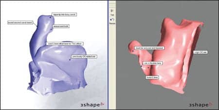
- Noting ear canal and conchal features. Having direct access to the patient’s ear, the dispenser becomes a primary resource for shell design input. Using software (eg, ScanIt), dispensers may apply 3-D “sticky notes” to specific features of the impression scan that require modification or special attention. Noteworthy features include anatomical variations, such as exaggerated end-bulbs; hyperacute bend angles; distended apertures; collapsing, conical, retrograde, and zetoid (z-shaped) canals; areas demonstrating significant TMJ effects or distensibility; stepped and narrow bony canals, and conical or short cartilaginous canals; inclusion cysts; exostoses; and other benign intracanalicular artifacts. Conchal issues include a potentially VC-occluding tragus; an antitragus blocking either microphone or VC; a narrow inter-tragal notch restricting VC positioning; and a dermatological need for a cut-back crus or helical areas.
- Creating templates. Certain otic anatomical features generate the need for application patterned overlays within the Shell Designer program called “templates.” Figure 4 demonstrates a CIC template designed by the author for application to the untoward combination of an extreme TMJ effect compounded by a narrow aperture.
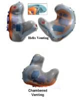
- Enhanced venting. Novel and consistent venting paradigms can be implemented. Stereolithographic shell production permits design and fabrication of other-than-linear tubular vents. Design of folded tubes, extended length horns, cavities, baffles, and reactive and resistive spaces provide the potential for less occlusion and greater otic aeration without feedback. Figure 5 presents some examples of custom vent designs that could be achieved only through the scan/print process.
- Noting impression defects. Impression artifacts can be highlighted for attention including oto-block string defects and gaps requiring virtual fill-in.
- Noting other anomalies. Non-artifacts such as impression voids due to exostoses, inclusion cysts, or meatal anomalies can be validated.
- Exact shell lengths. Desired shell canal lengths can be indicated exactly.
- Tapering. Canal tip tapers and special treatment for bony canal areas can be requested by in situ annotation.
- Precise offsets. Site-specific areas can be marked as requiring positive or negative offset (buildup or reduction) pre-specified in intervals as small as 100 microns (0.1 mm).
- Directional microphone positioning. Directional microphone orientation planes can be identified directly on the scan image.
- Remakes. Shell remakes can be specified in two or three dimensions using methods described below.
- Client demonstration. Given the opportunity to share both video otoscopy and impression scan software on duplicate viewing screens, patients and accompanying significant others are motivated and drawn into appreciating the technical nature of the custom hearing aid pre-fitting process.
- Filed for indefinite reuse. All original scan and annotation files reside on the dispenser’s computer for subsequent access and recall.
|
| FIGURE 5. Custom vent configurations unique to scan/print shell production (courtesy of Bob Manning, Starkey Laboratories). |
Once the impression has been scanned and an input.stl file created, the dispenser has the option to transmit the file via the Internet to the laboratory with performance specifications only. In fact, certain impression profiles provide obvious direction for shell design without dispenser-enhanced input.
|
| FIGURE 6. In-office impression scans with 3-D in situ morphological annotations provided by the dispenser. |
Specific Techniques for In-Office Scanning: New Orders
Valuable input can be added to the shell design process by the hearing care professional with the following enhancements:
Scanning with text annotations. Together with the scan file, the dispensing professional can include text-based annotations about morphology on the online custom hearing instrument order form. Examples of input variables are found in the impression-taking process flow chart (Figure 3). Scan files remain stored on the computer.
It is also possible for the dispensing professional to physically detail the impression with a Dremel-type tool in advance of scanning. This may be accomplished more effectively, without irreversible distortion of the original impression, using dispenser-oriented shell design software.
|
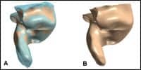
| FIGURE 7a-b. The author applies a production version of 3Shape’s Shell Designer to convert a) an impression with an end bulb in an relatively inflexible ear canal into b) a detailed canal with reduced end bulb and tapered canal tip. |
Scanning with graphically based annotations. Figure 6 shows how site-specific annotations may be affixed directly to the virtual impressions in 3-D.
Scanning with virtual detailing of the impression. Figure 7 illustrates how dispenser-oriented shell design software, currently in development, might be applied to the scanned impression. Manufacturing-oriented programs, such as 3Shape’s Shell Designer™, create a design “tree” that retains access to all prior stages of the input scan prior to modification and conversion to a virtual custom hearing instrument shell. The laboratory shell designer subsequently reviews the dispenser’s virtual detailing effort in context of the dispenser-requested shell morphology and performance characteristics.
Specific Techniques for In-Office Scanning: Remakes
Despite the enhanced degree of specificity in custom shell design, morphological modifications are not infrequently required to achieve a desired balance of otic comfort, freedom from feedback or extrusion, and cosmetic acceptability. For oversized shells, in-office modifications (within limits) may save an otherwise improbable fitting.
If these mechanical in-office shell modifications are satisfactory and do not compromise shell integrity, the fitting often requires no further morphological action. However, if the magnitude of shell modifications transcends the level of “in-office modification,” the dispensing process must be suspended with a concomitant loss of momentum in the fitting process. Typically, in these cases, the physical instrument is returned by the dispenser to the laboratory with a description of symptoms or a description of suggested modifications, often referring to the detailed shell as a likely candidate for remake. But with scan/print technology, because the virtual impression remains on file at the laboratory, a new impression is generally not required.
Important additional options are also available to the dispensing professional. If an effective ad hoc shell modification can be made in-office, the dispensing process momentum may be temporarily preserved with recourse to a remake-without aid (RWA), even if the basic shell integrity is compromised.
|
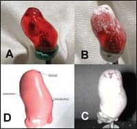
| FIGURE 8a-d. Actual shell remake without aid (clockwise): a) Before modification; b) Modified with Dremel-like tool; c) Prepared, and d) Scanned. |
The RWA has been a necessary procedure in the case of any in-warranty custom instrument loss. With invest/pour technology, instrument replacement either required a new impression or transmitting of an office-stored polysiloxane investment. Meriting general acceptance as a policy by custom hearing instrument manufacturers, the RWA offers significant benefits to the dispensing process and is especially suited for scan/print shell technology. In addition, the virtual redesign may be previewed online by the dispenser for approval prior to the actual physical remake.
For in-progress dispensing requiring shell remake, the output.stl image (shell) can be annotated with specific modifications and transmitted over the Internet to the laboratory. A new instrument is then fabricated with the same serial number. The RWA instrument incorporates the recommended morphological changes and is returned to the dispenser, who is charged a nominal fee. This fee is refundable when the previous instrument iteration is returned for credit (ie, RWA exchange).
This system maintains fitting continuity and momentum, engages the patient in the process, and greatly improves the likelihood of longer-term fitting effectiveness and consumer satisfaction. In certain difficult-to-fit cases, successive approximations to the morphological goal may require serial shell RWAs.
The dispenser is presented with the following scan/print-based alternative techniques for shell redesign and remake. Some of these can be implemented at this time through participating custom hearing instrument manufacturers, while other procedures are under development:
|
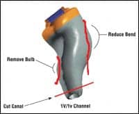
| FIGURE 9. 2-D annotated screen capture of the virtual hearing instrument showing required morphological improvements. |
Physical detailing and scanning of modified shells for remake. For fittings that can be characterized as “oversized,” apply a Dremel-type tool to achieve a comfortable, effective fit. Patch the shell as needed with UV-cure material. Then, spray coat the modified shell for laser opacity (ie, photo-developer spray), scan it, and transmit the modified, annotated shell scan to the laboratory for RWA, maintaining continuity for the patient in the fitting process (Figure 8). “Undersized” shells may be temporarily built up while an RWA replacement is ordered with the appropriate additional surface offset.
Ordering a remake using output.stl screen capture 2-D image markup. On the computer, recall the read-only output.stl file referenced to the instrument serial number (eg, via 3Shape’s Order Viewer™ software). Review the input.stl and output.stl relationship. Orient a two-dimensional view that best displays the shell or faceplate area(s) in need of modification. Screen capture the image and deploy a “paint” program to annotate the modifications required (Figure 9). E-mail the image as an attachment with the RWA request and modification details.
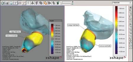
Ordering a remake using direct 3-D output.stl image markup (procedure under development). Through privileged account Internet access (eg, via 3Shape’s Order Viewer software), the dispenser can view read-only versions of every input.stl and output.stl image referenced to a specific instrument serial number. The dispenser can view binaural images of any impression, as well as the original shell and all remakes indexed over time. The shell of interest can be viewed within the virtual ear with independently variable degrees of transparency or opacity. 3-D notations can be appended to any shell image to direct remakes based on morphological need. Remakes may be previewed by the dispenser for approval prior to actual printing. (Figure 10).
|
| FIGURE 10. Prototype rendition of 3Shape’s Order Viewer™ software providing dispensers with Internet access to all impression and shell images associated with a specific instrument serial number. Virtual shells may be annotated for RWA redesign and remake. Color codes denote shell offset. |
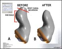
Ordering a remake by redesigning the output.stl file (procedure under development). Recall and download a duplicate design tree to a dispenser version of 3Shape’s Shell Designer. Make the actual design-tree modeling changes in the output.stl file (Figure 11). Upload the modified design tree to the laboratory for review, redesign as needed, then queue to the next stereolithography print batch for RWA.
Summary
|
| FIGURE 11a-b. Virtual correction of a morphologically problematic CIC shell by dispenser: a) Before redesign. End bulb made insertion difficult and extended wearing uncomfortable; bony canal incursion created pain on deep insertion and on operating the multi-memory response button; b) Patient complaints resolved after redesign with virtual detailing in Shell Designer. |
In the last 6 years, the entire custom hearing instrument industry has migrated from the invest/pour model to the scan/print model of custom hearing instrument shell design and production. The new manufacturing paradigm offers direct and significant benefits to dispensing professionals. By incorporating in-office impression scanning with appropriate morphological annotations, the dispenser enhances the opportunity for initial custom fitting success—especially with the consumer-preferred CIC morphology!
By accessing both input.stl (impression) and output.stl (shell) files, the dispenser gains a highly efficient and effective tool for both initial shell design and for RWA instrument remakes with no loss of momentum in the fitting process. The author believes that an industry need to directly engage dispensers in the new SPS technology will lead to the proliferation of dispenser-oriented virtual file viewing, annotating, and modification software within the next 18 to 24 months.
Acknowledgements
The author thanks Starkey Laboratories, especially Keith Guggenberger and Terry Ruzicka, for support in exploring potential dispenser applications of scan/print technology, as well as master shell designer Bob Manning and digital process engineer Craig Feldsien. 3Shape’s Tais Clausen provided access to both prototype hardware and software. Wife and esteemed colleague Carol has been invaluable to the creative process.
References
- Sullivan R. Why morphology matters: Practical dispensing applications of 21st century shell design technologies, Part 1. Hearing Review. 2008;15(2):12-19.
- Oliveira R, Babcock M, Venem M, Hoeker G, Parish B, Kolpe V. The dynamic ear canal and its implications. Hearing Review. 2005;12(2):18-19,82.
- Sullivan R. Resolving CIC fit problems via in-office modifications. Hear Jour. 2005;58(1):38-42.
- Gudmundsen G. Physical options for custom hearing aids. Sem Hear. 2003;24(4):313-321.
- Agnew J. A study of the stability of ear impression materials. Hear Jour. 1986;36(6):29-33
- Kolpe V, Oliveira R. Chemistry and rheology of otoplastic materials. Sem Hear. 2003;24(4):289-298.
- McHugh E, Purnish M. Evaluating the accuracy of ear impression materials. Hear Instrum. 1984:35(12):12.
- Nolan M, Combe E. In vitro considerations in the production of dimensionally accurate earmoulds. Part 1: The ear impressions. Scand Audiol. 1989;18(1):35-41.
- Okpojo A., Braden M. Development of a novel audiological clinical material. Biomaterials. 1993;14(1):21-25.
- Pirzanski C. Ear impressions for the new laser technology. Sem Hear. 2003;24(4):323-332.
- Pirzanski C. Earmolds and hearing aid shells: a tutorial. Hearing Review. 2006;13(5):39-46.
- Pirzanski C. Selecting material for impression taking: the case for standard-viscosity silicones. Hear Jour. 2000;53(10):45-50.
- Pirzanski C, Berge B. Is the end near for acoustic feedback? Hearing Review. 2004;11(4):18-23.
- Ingrao B. E-business: connecting hearing care professionals and their suppliers. Hearing Review. 2005;12(9):18-22.
Correspondence can be addressed to [email protected] or Roy F. Sullivan, PhD, at .


