Most people 20 years ago would not have predicted that behind-the-ear (BTE) hearing aids would become the dominant style used by people with hearing loss in America. Things certainly have changed. The latest industry statistics showed that 50.2% of hearing aids sold in the first half of 2007 were BTEs.1 Although a statistical breakdown of the specific styles of BTEs is not readily apparent, it is likely that a majority of BTEs fitted are in the thin-tube, open-ear style. Many of these are micro-size BTEs. Clearly, aesthetic appeal is one of the key driving forces in this reversal of fortune.
Considerations in Designing a Micro-size BTE
Designing a micro-size BTE hearing aid is not as straightforward as it may appear. While it is expected that the micro-size hearing aid has to be small and attractive, the final “look” of the micro-size device is the result of a series of considerations and compromises made relative to functionality and performance.
Functionality. The size and the number of components that can be packaged inside a micro-size BTE case are limited. Thus, the designers’ perceived importance of a particular feature determines which function(s) may be sacrificed to achieve the small size.
In exchange for the smaller size, a micro-size hearing aid typically does not have a telecoil and the capability to accept direct audio input (such as the use of FM and CROS type fitting). The receiver may be limited in size and output. Fewer user controls, such as a volume control or a program button, are available. In addition, the size of the battery is typically smaller than that used in standard-size BTEs, and this might also mean greater difficulty for the users when changing the batteries.
These limitations could have significant implications on the acceptability of the device to wearers. The limited output of the receiver suggests that the fitting range of the device is limited to individuals with up to a moderate-to-severe hearing loss, unless some other means to boost the real-ear output of the hearing aid is utilized (such as lengthening the depth of insertion of the earmold or placing the occluding receiver deep into the ear canal). The lack of a telecoil could hamper the use of the hearing aid in a looped environment; however, it may not affect its use on the telephone provided that an effective active feedback cancellation algorithm is used in the hearing aid. The smaller battery means that the hearing aid must have a low current drain in order to have a reasonable battery life. On the other hand, the lack of DAI and the smaller battery (and the difficulty of handling it) should be discussed with the wearers prior to the fitting to set the right expectations.
Signal-processing performance. While cosmetics are important, it is generally unacceptable to most dispensing professionals and wearers if the micro-size hearing aid does not perform as well as, or better than, a standard-size BTE.
One aspect of performance that may be affected by the size of the hearing aid case is the signal-to-noise ratio (SNR) advantage offered by the directional microphone used on some of the micro-size hearing aids. This is because the smaller BTE case could restrict the placement options of the microphone openings.
A directional microphone achieves its intended function of SNR enhancement by reducing the sensitivity of the microphone system to sounds that originate from the sides and back. In so doing, the relative level of the sounds from the front is higher than that from the sides and back. Assuming that sounds from the front are desirable and sounds from the back are undesirable, SNR is improved. Typically, the theoretical directional advantage in a diffuse field is reported by its directivity index (DI).2

|
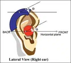
| FIGURE 1. Illustration of the angular deviation between the angle formed by the microphone alignment and the horizontal plane. The red circle simulates the faceplate of an ITE hearing aid, while the blue semicircle simulates the BTE case. The two light-blue circles are the front and rear microphone openings. |
A directional system typically utilizes two omnidirectional microphones that are placed at a fixed separation to achieve its stated DI. Typically, inputs from the rear microphone are delayed relative to that received from the front microphone. Input from the rear microphone is then subtracted from that of the front microphone. The “difference signal” is then processed by the various signal-processing algorithms of the hearing aid.
Most of the discussions on directional microphones assume that the sound sources are on the same horizontal plane as the microphones. Most assume that the angle formed by the alignment of the two microphones and the horizontal (and sagittal) planes is zero (0°). Figure 1 shows the lateral view of the right ear with a directional ITE (red circle) and BTE (blue semicircle). The horizontal plane is indicated as the horizontal line, while the two microphone openings are represented as circles. In an ideal situation (and for maximum directional benefit), the two openings are in line with the horizontal plane.
In reality, when a hearing aid with a directional microphone (ITE or BTE) is placed on the wearer’s head, the angle between the ports would deviate substantially from zero, leading to a reduction in the effectiveness of the directional microphone. The extent of reduction depends on how much angular deviation occurs in both the horizontal and sagittal planes.
Assuming an ideal free-field situation, the extent of DI reduction may be roughly estimated from the magnitude of the angular deviation using the following equations:
Equation #1:
E’ = E cos(θ)
…where E is the full effectiveness, and E’ is the observed effectiveness; E equals 2 for a dual mic system.
Equation #2:
DI = 20 logE’
…where DI is the calculated directivity index. For example, if the angle formed by the microphone alignment and the horizontal plane is 0°, cos(0) becomes 1 and E’ = E. This means that the theoretical advantage of the directional microphone is fully realized. For a dual microphone system, E has a theoretical value of “2.” This would yield a DI of 6 dB.

|
| FIGURE 2. Theoretical relationship between directivity index (x-axis) and angular deviation of microphone alignment (y-axis) from the horizontal plane. |
On the other hand, if the angle is 20°, the cos(40) becomes 0.94 This means 94% of the theoretical advantage of the directional microphone may be realized. Using Equation 2, an elevation of 20° would yield a DI of 5.5 dB (ie, 20 log[1.88]). Figure 2 shows the effective DI as a function of the elevation angle.
Clearly, small deviations do not affect the DI significantly. The decrease in DI is around 1 dB for angular deviation less than 30°. As the deviation increases beyond 35°, the decrease in DI accelerates. The theoretical DI of 6 dB becomes 0 dB at a deviation of 60°. Obviously, in real-life environments, any head movement by the wearer would change the elevation angle and lead to deviation from the theoretical DI. Nonetheless, it is important to bear in mind such relationships when designing a micro-size BTE case.
Despite the importance of a small angular deviation in order to preserve the SNR advantage of a directional microphone, one should also recognize that SNR improvement may be achieved through the use of post-microphone processing algorithms, such as a noise reduction (NR) system. The effectiveness would depend on the complexity of such an algorithm and its interactions with the directional system.
A New Micro-BTE System
Recently, a micro-size BTE hearing aid that can be fitted using either conventional earhook/earmold or a thin-tube, open-ear earset was introduced by Widex. The thin-tube fitting can be used in conjunction with a specialized laser-shell earmold (élan flex mold) to fit people with as much as 70 dB of hearing loss across frequencies. The hearing aid comes in six different two-tone color cases and is available in all Widex products using the Integrated Signal Processing (ISP) platform (ie, Inteo m-model, Aikia m-model, and Flash m-model for the premier, high-end, and mid-level categories). Figure 3 compares the size of the Inteo-m model to the Inteo IN-9 model.

|
| FIGURE 3. Size comparison between the IN-m (right, dark gray) and the IN-9 (left, beige color) hearing aids in an open-fit configuration. |
The Inteo m-model runs on the ISP platform; thus, it has all the features available on the Inteo hearing aids (readers are referred to Kuk3 for a review of the key features). Briefly, the Inteo is a 15-channel hearing aid that has an input dynamic range of 107 dB SPL, a low compression threshold in each of the 15 independent channels, a noise reduction algorithm that increases listening comfort in noise, a speech enhancer that maximizes the speech intelligibility index (SII) in noise,4 a 15-channel fully adaptive directional microphone, and a multidirectional active feedback cancellation algorithm that increases usable in situ gain by 12 to 15 dB,5 and minimizes the occurrence of feedback. In addition, there is also a linear frequency transposition algorithm that is proven to improve consonant recognition for people with a high-frequency hearing loss.6
In finalizing the design of the micro-size case, a decision was made to keep its resemblance to traditional hearing aids while reducing its size without affecting its performance. And, in cases where a compromise is unavoidable, it has been designed so that only minimal inconvenience may be encountered. For example, the m-model does not have a telecoil or DAI capability. On the other hand, because of the efficacy of the active feedback cancellation algorithm, use of the Inteo-m on the telephone in a “microphone” mode is virtually problem-free. Furthermore, the Inteo-m has an excellent cell phone compatibility rating of M4 (on a 1-4 scale). When used with a compatible cell phone, the wearer is almost guaranteed interference-free use of the cell phone (assuming that the cell phone has an immunity rating of 2 or higher).
An optional remote control is available to allow program and volume control changes. Despite the use of a size #10 battery in the Inteo-m model, the fact that the current drain is only 0.7 mA means that it will take 120 hours (1 to 2 weeks use) for a battery to be depleted.
The case of the m-model was designed to resemble a modern, high-tech hearing aid. It was decided that the two microphones should be placed with openings on both sides of the m-model case. This would prevent moisture and debris from directly depositing onto the microphone surface and minimizes the need for repair from microphone damage. The deviation of the microphone alignment from the horizontal plane will likely vary depending on the wearer pinna characteristics.
Thus, we conducted the current study to examine the in situ microphone alignment of the Inteo m-model hearing aid, and the effectiveness of the directional microphone and noise reduction systems in improving SNRs. For comparison purposes, the Inteo IN-9 hearing aid was also included in the evaluation.
Study of Directionality and Microphone Alignment
Subjects. A total of 19 subjects with various degrees of sensorineural hearing losses participated in the study. All subjects had a moderate-to-severe degree of hearing loss in the high frequencies. The hearing thresholds for 9 subjects were less than 30 dB HL at 500 Hz. These subjects were fitted with the thin-tube open-ear élan earset. The hearing thresholds at 500 Hz were greater than 30 dBHL for 10 subjects, and these people were fitted with their own earmolds or an occluded foam plug as earmolds during testing.
Procedure. Each subject was tested with both the Inteo IN-m hearing aid and the Inteo IN-9 hearing aid in a counterbalanced manner. Binaural fitting was used for all subjects.
The angle formed between the microphone alignment and the horizontal plane was first measured on all subjects with both hearing aids coupled to the appropriate earmolds. To measure the horizontal deviation, we devised a measurement tool that used an angle-linear ruler in conjunction with a level meter. This measurement was done for both the IN-9 and the IN-m hearing aids, and for both ears of each subject.
The SNR improvement provided by the different features on the IN-m and IN-9 hearing aids was evaluated using the Hearing In-Noise Test (HINT). The speech-shaped noise was presented at an overall level of 75 dB SPL from 90°, 180°, and 270°. The noise was presented 30 seconds prior to the onset of the speech stimulus and was presented continuously.
Both hearing aids were set and evaluated under six hearing aid test conditions: 1) omnidirectional mic alone (omni); 2) omnidirectional mic with noise reduction (omni+NR); 3) omnidirectional mic with speech enhancer (omni+SE); 4) directional mic alone (dir); 5) directional mic with noise reduction (dir+NR); and 6) directional mic with speech enhancer (dir+SE).
During the tests, subjects were instructed to sit still for the whole test presentation. To make sure that there was no unintended movement, subjects rested their chins on a parallel bar during the entire test. All testing was done in a sound-treated booth.

|
| FIGURE 4. Scatter-plot showing the relationship between the angular deviations measured with the IN-m micro-size hearing aid and the IN-9 traditional BTE. |
Test Results
Differences in angular deviation between the IN-9 and the IN-m. Figure 4 shows the relationship in the angular deviation of the microphone alignment from the horizontal plane between the IN-m and the IN-9 hearing aids. A diagonal was also included in the graph to indicate the relative angles between the two hearing aids. Data points that fell on the diagonal would suggest identical angles between the IN-9 and the IN-m. Data points above the diagonal would suggest that the angular deviation of the IN-m is greater than the angular deviation of the IN-9. Data points below the diagonal would suggest otherwise.
The majority of the data points were above the diagonal (Figure 4). This suggests that the angles formed in the IN-m micro-size hearing aid were typically larger than those formed in the IN-9 BTE. There was only one subject whose angles were smaller with the IN-m than the IN-9.
Additionally, the angles measured with the IN-9 ranged between 10° and 20°, with the majority of data points at around 15°. The angles measured with the IN-m ranged between 20° and 35°, with the majority of data points around 25° to 30°. The range of angular deviation was larger in the IN-m micro hearing aid (10° to 40°) than the IN-9 hearing aid (10° to 30°).
More importantly, none of the subjects showed an angular deviation greater than 40°. Using Figure 2 as a guide, this would suggest that the SNR of the microphone used in the IN-m may be 1 dB poorer than that provided by the IN-9 BTE hearing aid.

|
| FIGURE 5A-B. Absolute signal-to-noise ratio (SNR) measured with the IN-9 (blue bars) and the IN-m (red bars) when the hearing aids were set in different configurations in (top) thin-tube open-ear fitting (n=9), and (bottom) conventional closed earmold fitting (n=10). |
Signal-to-noise ratio difference between the IN-9 and IN-m. Figure 5 summarizes the absolute SNRs required for 50% performance on the HINT. Figure 5a (top) summarizes the results when the hearing aids were fitted in an open-ear manner, while Figure 5b (bottom) shows the results when the hearing aids were fitted with a standard (or occluded) earmold configuration. The higher the absolute SNR, the poorer was the performance in noise.
Thin-tube open-ear fitting. Figure 5a shows that the average subject required a SNR of 4 dB when the hearing aids were in an “omni” mode. That requirement changed to 3 dB with the “omni+NR” mode and around 2 dB with the “omni+SE” mode. The SNR further decreased to 1 dB in the “dir” mode alone and stayed at around 0 dB for the “dir+NR” and “dir+SE” conditions. Similar findings were observed for the IN-9 and the IN-m micro-size hearing aid. This suggests that:
- The IN-9 and IN-m, despite their differences in angular deviations, performed similarly in noise;
- SNR advantage offered by the directional microphone, even in the open-ear fitting, was around 3 dB (omni minus dir; omni+NR minus dir+NR; omni+SE minus dir+SE) for both the IN-9 and IN-m;
- The SNR advantage of the SE was about 2 dB in the omnidirectional mode and 1 dB in the directional mode; and
- The SNR advantage offered by the “dir+SE” mode over the “omni” mode was around 4 dB. This was higher than what was reported previously on the Diva élan open-ear hearing aid.7
Conventional closed-mold fitting. Figure 5b shows that the average subject required a SNR of over 6 dB when the hearing aids were in an “omni” mode. That requirement changed to 5 dB with the “omni+NR” mode and less than 4 dB with the “omni+SE” mode. The SNR further decreased to -1 dB to 1 dB in the “dir” mode alone and stayed at around -1 dB for the “dir+NR” and -2 dB for the “dir+SE” conditions. Similar SNRs were observed for the IN-9 and the IN-m micro-size hearing aids across all conditions. This suggests that:
- The IN-9 and IN-m, despite the difference in angular deviation, performed similarly in noise;
- SNR advantage offered by the directional microphone was around 6-7 dB (omni minus dir; omni+NR minus dir+NR; omni+SE minus dir+SE) for both the IN-9 and IN-m;
- The SNR advantage of the SE was about 2-3 dB; and
- The SNR advantage offered by the “dir+SE” mode over the “omni” mode was over 8 dB.
Discussion
Overall, this study showed that:
- The angular deviation in the IN-9 was small, typically between 10° and 20°, and
- The angular deviation in the micro-size IN-m was greater than the IN-9, but was typically between 20° to 35° for the majority of subjects.
Despite the differences in angular deviation, the SNR performance of the directional microphone in the IN-m was similar to that of the IN-9, and ranged from 3 dB improvement in an open-ear fitting to 6 dB in a closed-ear fitting. When the speech enhancer was also included, the SNR advantage over an omnidirectional microphone alone improved to 4 dB in an open-ear mode to 8 dB in a closed-ear mold. This confirms that not only does the IN-m micro-size hearing aid look good, but it also works well in the presence of background noise.
A practical question that clinicians may raise is the need to determine the angular deviation of the directional BTE (and ITE) as part of their clinical practice. There can be two parts to this question. The first relates to the general need for measuring the angle in all hearing aids, especially the micro-size hearing aids. The second relates to the specific need when it comes to the m-model hearing aids.
The answer to the first question is a definite “yes.” This is supported by the theoretical consideration on the decrease of the DI as a function of the angular deviation. However, Figure 2 shows that a small deviation does not affect the DI too much. Angular deviation of 20° leads to less than 0.5 dB decrease in DI, and 30° to 40° may lead to 2 dB decrease in DI. Unless the angular deviation is significantly greater than this and there is no post-microphone processing to enhance the SNR, the decrease in SNR benefit would probably be insignificant. Obviously, this would be dependent on the design of the micro-size hearing aid and its interaction with the individual wearer.

|
| Why Don’t Directional Microphones Work Better? by Ryan J. Mills, MA, and Doug Martin, PhD. in September 2007 HR. |
The second question relates to the need for angular deviation measurement in the m-model in particular. Data from this study suggest that, while such an measurement may be useful, it is not necessary. There may be several reasons. First, the majority of subjects in this study showed less than 35° of deviation from the horizontal plane. And, if the subject population used in this study is representative of the population at large, one would conclude that a majority of subjects would receive the same SNR benefits from the IN-m micro-size hearing aid as they would from a more traditional mini-BTE hearing aid. Measuring the angle would not provide additional information.
The second issue is the impact of this deviation. As we have shown, there may be a theoretical difference of 1 dB to 1.5 dB difference in directivity provided by the hearing aid; however, in reality, there was no performance difference between the IN-9 and IN-m. A reason for this lack of difference may be explained by the additional signal processing provided by the post-microphone processing algorithms used within the hearing aid. In this case, the subsequent noise reduction algorithm may offset the loss in SNR advantage. Whereas the contribution of the NR may be minimal in improving the SNR when the directional microphone is fully effective, the contribution of the NR will be increased when the directional microphone is less effective.
This suggests that for maximum real-world effectiveness in noisy situations, a hearing aid should have both a directional microphone and an effective noise reduction algorithm so they may complement each other under different acoustic environments (see Kuk and Paludan-Muller4 for a detailed discussion).
Because of the potential that post-microphone processing may further enhance (or degrade) the actions of the microphone system, a better use of clinical time is to measure the speech-in-noise performance of the hearing aid rather than measuring the angular deviation of the microphones. This practice will provide a more complete evaluation of the whole hearing aid system, and not limit one’s assessment to a single performance aspect.
This article was submitted to HR by Francis Kuk, PhD, director of audiology, and Denise Keenan, MA, a research audiologist (respectively) at the Widex Office of Research in Clinical Amplification (ORCA), Lisle, Ill, and Lars Baekgaard, a research engineer at Widex A/S, Vaerloese, Denmark. Correspondence can be addressed to [email protected] or Francis Kuk, PhD, at .
References
- Strom KE. Slower growth in the first half of ’07. Hearing Review. 2007;14(9):8.
- Ricketts T. Directional hearing aids. Trends Amplif. 2001;5(4):139-176.
- Kuk F. Integrated signal processing–a new standard in hearing aid processing. Hearing Review. 2006;13(3)[suppl].
- Kuk F, Paludan-Muller C. Noise management algorithm may improve speech intelligibility in noise. Hear Jour. 2006;59(4):62-65.
- Kuk F, Jessen A, Klingby K, Henningsen L, Peeters H, Keenan D. Changing with the times: additional criteria to judge the effectiveness of active feedback cancellation algorithm. Hearing Review. 2006;13(9):38-48.
- Kuk F, Peeters H, Keenan D, Lau C. Use of frequency transposition in thin-tube, open-ear fittings. Hear Jour. 2007;60(4):59-63.
- Kuk F, Keenan D, Sonne M, Ludvigsen C. Efficacy of an open fitting hearing aid. Hearing Review. 2005;12(2):26-32.