Part 4: BTE Styles, Materials, and Acoustic Modifications
|

A series of articles on one of the most critical—and problematic—parts of the hearing instrument fitting process.
An earmold is an individually fabricated ear insert that channels the sound reproduced by a hearing aid receiver to the eardrum. Before making a decision on the earmold style and material, several considerations must be taken. The evaluation should include: severity and type of the patient’s hearing loss, anatomical properties of the ear, patient’s manual dexterity, allergic conditions, personal preferences, and difficulty with any previous hearing instrument fitting.
Earmold Styles
Earmolds are made in two basic styles: concha and canal. Each style has several sub-styles that differ mainly in cosmetics. Common earmold styles are shown in Figure 1. These images of earmolds were digitally modeled by Dreve, Germany.1

Concha earmolds occupy the ear concha and canal, and can be made in the standard, shell, skeleton, or non-occluding configurations. The standard earmold fits in the entire concha. The shell earmold has the bowl shelled out for an enhanced cosmetic appeal. In the skeleton earmold the concha is reduced even further to a ring, or 1/2-ring. Concha earmolds can be made with an extended helix for better retention.
Canal style earmolds include the half-shell, canal, and canal-lock configurations. The half-shell earmold occupies the cavum-concha; the canal earmold fits in the canal aperture; the canal-lock earmold possesses a small plastic tail (lock) extended to the ear concha.
Earmold Style Selection
The most common concerns in selecting the earmold style are acoustic seal, retention, insertion, and comfort.
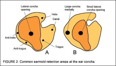
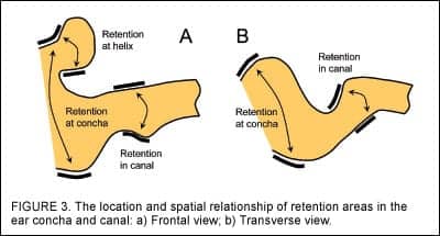
Retention. To have a secure fit, an earmold should have adequate retention in the ear. Any area on the earmold body that is larger medially than laterally provides retention. Figure 2a shows earmold retention areas in the lateral view. These areas include the canal, tragus, antitragus, and helix.2 Figure 3 shows how retention surfaces are positioned in the ear.
The secure fit of canal-style earmolds depends entirely on retention areas available in the ear canal. Unfortunately, there are ear canals that lack retention areas. In these cases the earmold can be made with an extension to the concha called a canal lock. The lock extends to the antitragus, rests against it, and prevents the earmold from moving out of the canal (Figure 4). In some ears the antitragus area may be open and render the lock ineffective.

Mandibular movements are a common culprit in making earmolds move laterally. Although the earmold shown in Figure 5 has a well-defined retention area in the ear canal, the widening of the canal resulting from jaw movements can loosen the earmold to the extent that it will be able to work out of the canal. Manufacturing the earmold from an open-mouth impression would eliminate the gap and provide a more secure fit.

For ears that lack sufficient retention in the canal area, full-concha earmolds are recommended. However, if a skeleton mold is to fit securely, the concha ring must rest against the lateral concha wall. as in Figure 6a. This may not be possible in fittings that have the thickness of the concha ring reduced in an attempt to make the earmold cosmetically appealing. If the ring does not provide retention, the earmold can be dislodged, break the seal in the canal and trigger feedback. Standard and shell earmolds that are not styled as much offer a more secure fit and pose a lower risk of acoustic feedback. That is why the standard and shell earmolds are often credited for “superior seal.”3

Mandibular movements not only widen the ear canal but also, in some ears, change the angle between the ear canal and concha. As a result, a hard-body full-concha mold can be forced out of the ear. This problem can be remedied in two ways:
1) If the ear provides adequate in-canal retention, use a silicone canal earmold. If it does not:
2) Use a silicone skeleton earmold. The earmold’s flexible concha ring will absorb the tissue movement while the canal area maintains effective seal.
A common reason for an insecure earmold fitting is excessive tightness. An earmold that is too tight may not be properly and completely inserted into the ear and will act as a “loose” earmold.
If an earmold is to support a considerably heavy device, such as an extended microphone or a larger receiver, making the earmold with an extended helix may be a worthy option. However, this option should be carefully considered because earmolds with oversized retention areas may be more difficult to insert.
Insertion. It is debatable which earmold style makes the mold easier for insertion. Some like the canal mold because it slides in easily without the need for proper helix positioning. Others prefer the half-shell style as the bulk of concha helps to guide the earmold into the canal. And some like the full concha style, particularly the skeleton mold.
One of the reasons for difficult earmold insertion is that a new patient may unintentionally rotate his/her hand holding the instrument while bringing it to ear level. Therefore, they will attempt to insert the earmold with its helix, or upper bowl, positioned backwards across the ear. The presence of the concha may help guide proper insertion.
As far as the shape of the patient’s ear is concerned, insertion problems may relate to:
• Deep tragus, antitragus, and/or anti-helix area;
• Helix area extended towards the ear canal;
• “Bottle neck” at the canal aperture;
• Sharp upward angle in the ear canal;
• Sharp first and second bends in the ear canal; or
• Constriction in the canal.
Earmolds that are made with excessively large retention areas are difficult to insert. Figure 2b shows an earmold that has the concha area much larger than the lateral concha opening in the ear. Certainly, inserting this earmold will be a challenge. A problem with insertion may also occur when the helix area on the earmold has a mushroom shape, or there is a constriction between the helix and the canal, or both, as shown in Figure 7. Since retention areas at the concha and helix are not a part of the earmold acoustic seal, they may be reduced to facilitate insertion.

Even a properly shaped earmold may be difficult to insert if the patient pushes the earmold in the ear canal horizontally. In ears where the canal rises sharply upward, the earmold may not go in, or will go in scratching and hurting the ear. In such ears the earmold should be pushed upwards to the ear canal (see Figure 4).
A lubricant, such as Oto-Ease™, can be used to facilitate insertion. However, lubrication may lead to a partial or complete blockage of the sound bore, and is often inconvenient for the patient.
Acoustic Seal. Contrary to the common belief that “the more the ear concha is occupied by the earmold, the more effective the seal,” two separate studies found that all earmold styles are capable of providing an equally effective acoustic seal. Kuk4 found that there was no difference in REIG among the shell, canal, and skeleton earmolds, while the standard earmold permitted the least amount of maximum REIG (Figure 8). Analyzing REAT data, Pirzanski5 noted that, in most subjects, canal earmolds sealed as effectively as standard earmolds—if not better. In both studies, the differences measured in sealing effectiveness among the earmolds were considered minor.

These findings further support the supposition that acoustic seal in earmolds (and also ear-level custom hearing instruments) occurs in the ear canal. This means that the bulk of the earmold at the concha is irrelevant to the earmold’s seal. However, it should be clearly stated that the above opinion is correct only if:
• The ear impression is properly taken;
• Structures of the patient’s ear provide sufficient in-canal retention,
• Mandibular movements do not break the seal, and
• The earmold is skillfully manufactured.
Obviously, all these conditions are not always met.
The sound escaping from the ear canal always follows the shortest path to the aid’s microphone. This path runs along the canal wall (commonly the front wall), above the tragus, and straight toward the hearing aid microphone. A larger earmold concha, an extended helix, or a raised tragus will not prevent acoustic feedback because the concha, helix, and tragus do not contribute to the earmold seal. They are simply not in the path of the leaking sound. Although the tragus area seems to provide additional seal, in reality it does not because the tragus forms a protrusion over the line of the head, and the leaking sound escapes sideways.
The practice of fitting full-concha earmolds to prevent feedback should be reconsidered unless earmold retention or patient dexterity is an issue. The impression-taking technique appears to be far more critical for the earmold proper acoustic seal than the earmold style. For enhanced seal, the impression should be taken with a higher viscosity silicone when the patient’s mouth is wide open, supported with a mouth prop (OM-HV impression). For a tutorial on this method, see Part 2 of this series in the May HR.
All ear impressions should be taken with the canal long enough to imprint any constriction in the ear canal. If the constriction is not shown in the impression, the resulting instrument may have the sound bore, vent, or both blocked against the ear wall (Figure 6b).
Comfort. To be comfortable, an earmold should fit snugly in the canal cartilage area and make no contact with the canal bony portion. The snug fit of the earmold is determined by several factors, including the impression-taking technique and material, and in-lab impression trimming and coating. Comfort for deeply fitting earmolds is achieved through in-lab impression trimming. While the earmold takes full advantage of the retention area at the canal second bend, it does not make contact with the ear wall past the bend where the canal is firmer and more sensitive (to see an illustration of this, see Figure 2 in Part 1, April HR, p 16).
In some ears mandibular movements are able to shift the earmold in the concha. The shifting may cause ear tissue soreness and discomfort. A canal style earmold should be selected for patients affected by this condition.
Earmold Materials
Most earmold labs offer, often under different names and different prices, the following earmold materials: 1) Hard acrylic (Lucite); 2) Hard light curing (UV) resin; 3) Soft acrylic; 4) Soft light curing resin; 5) Medical grade silicone; 6) Vinyl; and 7) Polyethylene.
Earmold materials vary in their physical properties, particularly in the degree of softness, extent of shrinkage, and finishing characteristics.
Shore value. The softness of a given material is described as the shore value. Earmolds made from a soft acrylic or soft ultra-violet material have 40 to 50 A Shore hardness, vinyl earmolds 30 to 50, and silicone earmolds 20 to 70, depending on the material and manufacturer. The lower the shore value, the more flexible the material. Earmolds made from silicones softer than 25 A Shore may not be firm enough for insertion into the ear. (Refer to Part 1 of this article in the April HR for a more in-depth discussion of this topic.)
Earmold Material Selection
Earmold acoustic seal and comfort are commonly the key concerns in selecting the earmold material.
Acoustic Seal. Proper acoustic seal between the earmold and the ear canal is necessary to prevent the occurrence of acoustic feedback. Traditionally, the effectiveness of an earmold seal is controlled through the thickness of impression coating, commonly made of wax. The problem is that wax adheres in different thickness at different points of the impression. This is because the impression is curved and thus retains wax differently at various locations. This may distort the shape of the earmold.
Fifield6 wondered whether there was a better method of improving the earmold acoustic seal than waxing. He developed the multilayer impression,7 a technique in which the impression was taken in several stages to maximize canal cartilage stretching in order to obtain an airtight seal. This technique was time consuming and never gained significant popularity. However, before it faded out, several interesting studies and observations were made.

Macrae8 compared the effectiveness of earmold seal relative to various molding conditions. His study was conducted as follows: Two impressions were taken from the same ear of 16 subjects. The first was taken following the traditional technique; the other was a multilayer impression. Four wax coatings of varying thickness were used to make four earmolds from the first impression, one earmold for each coating condition. Earmolds A were made with the thinnest impression coating, whereas earmolds D with the thickest (Figure 9). Multilayer impressions were not coated prior to making earmolds E. All earmolds were made from the same silicone. A pressure seal test was administered to establish the efficiency of each earmold sealing.
He found that the seal varied significantly among earmolds and strongly depended on the thickness of the wax applied to the impression: Earmolds A sealed in only 15% of the cases, whereas earmolds D sealed in 65%. Generally, the thicker the coating, the more effective the seal was. Interestingly, Earmolds E made from non-waxed multilayer impressions sealed most effectively, reaching 88%. This better seal was achieved despite the fact that Earmolds E had smaller canal diameters than the extra-tight Earmolds D. Earmolds C, which had on average the same canal diameter as Earmolds E, provided a much less effective seal (50%).
This surprising fact can be explained as follows: The ear canal tissue is soft, but its softness is not a rubber-like flexibility. Certain areas of the cartilage appear to be more forgiving than others (see discussion on ear canal dynamics in Part 2 of this series). The extra-tight Earmolds D did not correspond properly with the anatomical structures of the subjects’ ears. They over-stretched the cartilage in some areas but did not stretch it enough in other areas allowing for a relatively poor seal and leakage. The most effective seal in Earmolds E was achieved by the employment of the multilayer impression. Although the impression stretched the ear tissue significantly more than the traditional impression, the stretching reflected the natural cartilage forgiveness. Therefore the fit of the resulting earmold was anatomically most accurate.
Canal cartilage stretching is most desirable and beneficial for hearing instrument fittings under the condition that it is carried out through impression taking, not through thicker impression waxing.
It is doubtful that soft earmolds can prevent acoustic feedback by “adjusting” to the shape of the ear.9 A loosely fitting soft earmold is smaller than the actual patient’s ear and allows for sound leakage around the earmold. When this earmold is forced deeper into the ear, the leakage may be reduced and feedback eliminated. This, however, will distort the earmold shape, and in most cases, it will not bring a lasting effect. The earmold will eventually recover from the stress applied and become loose again.
There are some thermoplastic materials that soften under body temperature. However, it should not be assumed that an increase in earmold softness will improve its seal. A loose-fit earmold will not become tighter just because the material becomes softer.
There were some experiments in manufacturing earmolds from thermoplastics that expanded in the patient’s ear under body temperature and provided an airtight seal within minutes of insertion. The presumption was that the ear tissue would stretch and conform to the tighter earmold whereas the softness of the earmold would prevent discomfort. While some patients benefited from the new material, others complained of the excessive tightness after the earmold expanded in the ear. As for the general patient population, the idea of manufacturing self-sealing earmolds was never successful.
Soft earmolds do not prevent acoustic feedback related to jaw movements. Consider that the increase in the ear canal volume would require the earmold to expand instantaneously when the mouth is opening and then compress just as quickly when the mouth was closing (see Figure 5). There are no soft earmolds that increase and decrease their volume in a split second. The likelihood of breaking the acoustic seal by jaw movements for both soft and hard earmolds is similar.5
Another study tried to determine whether clinicians fit soft or hard earmolds more successfully.10 A total of 2,731 earmolds were investigated: 1,318 of the earmolds were made from soft materials such as silicone, vinyl, and soft acrylic, while the rest were made from hard acrylic. The parameters of the molding process were monitored throughout the study to ensure consistent manufacturing. The study found that soft earmolds required 0.6% more remakes than hard earmolds. This demonstrates that there is no reason to consider soft materials superior.
This assurance regarding the equal sealing properties of both hard and soft earmolds may be inconsistent with the field experience of some clinicians who recognize that, in their practice, soft earmolds—particularly those made from silicone—are less susceptible to acoustic feedback than hard Lucite earmolds. Certainly, this can be true.
The explanation is that the better seal with some silicone earmolds is related to the fact that silicone earmolds shrink only 0.2% during the molding process and do not require any surface treatment. In contrast, hard Lucite earmolds shrink 2%-4% during polymerization and require extensive buffing and shining to make them cosmetically appealing. This reduces their dimensions and adversely affects their sealing properties.
To compensate for the shrinkage and buffing, impressions for Lucite earmolds must receive a slightly thicker coating of wax compared to impressions for silicone earmolds. If the lab does not differentiate the parameters of the coating process, Lucite earmolds will have inferior sealing compared to silicone earmolds. The difference in waxing is minor, but the effect on earmold sealing is major: An earmold that is merely 0.2 mm loose around the circumference of the earmold will allow for the same sound leakage that would occur through a 2 mm vent. In contrast, an earmold that is 0.2 mm tight will not adversely affect fitting comfort.
Inadequate in-lab impression coating for hard earmolds may be the reason why silicone earmolds are often credited with a more effective seal.
Insertion. While inserting a soft earmold, the patient may have difficulty guiding the canal portion of the earmold into the ear canal. As a result, the canal on the earmold can bend backwards, resulting in improper insertion. Hard earmolds are more suitable for these patients.
Comfort. Theoretically, earmolds made from soft materials should be more comfortable than those made from hard materials. Practically, because most ears appear to be softer than most earmolds, the softness of the earmold is irrelevant. It is the ear tissue that has to conform to the earmold, not the earmold to the ear.
Results in custom hearing aid fittings confirm this opinion. The majority of shells for custom hearing instruments are manufactured from either a hard acrylic or hard ultraviolet resin. A study found that, with proper impression taking technique and competent manufacturing, less than 1% of custom in-the-ear hearing aids required a remake due to discomfort, including high gain instruments.11 These results would not be so impressive if soft materials were as critical for comfort as it is commonly thought.
Allergic Conditions. Hard and soft materials used to manufacture earmolds are biocompatible so they generally do not cause irritation or sensitization to the skin in the ear. However, some patients can exhibit high sensitivity to traces of certain chemicals (particularly those found in acrylic resins) and develop soreness of the ear tissue. For these patients, the use of a hypoallergenic earmold material is recommended. The challenge is that there is not one hypoallergenic material that is good for all patients with allergies. Commonly clear ultra-violet resin (for hard earmolds and earshells) and clear silicone (for soft molds) are considered best. Unfortunately, some patients can still be allergic to these plastics.
To determine which earmold material is most hypoallergenic for a given patient, the clinician may administer a skin patch test, where small samples of earmold materials, provided by the earmold lab, are taped to the patient’s arm or neck. The earmold material that does not result in an adverse reaction should be used for the earmold.
Pediatric earmolds. Colors are popular with children and are often requested to match the color of the BTE hearing aid casing. The parents of very young children being fit with hearing aids for the first time may not want bright colored earmolds that “attract attention” to the child’s hearing loss. Take this as a possible sign that the parents are still working through some emotional issues with acceptance of their child’s hearing loss. You may help to negotiate a compromise (eg, a bright BTE casing and a skin-tinted earmold to make the parents more accepting).
Earmolds for children can be made from different colors for right and left ears to help first timers identify which earmold (and hearing aid) goes on which ear. Little girls often love the “rainbow swirl” colors or the “glitter” earmolds. For older children, hard Lucite earmolds can be ordered with a logo of a sports team or a cartoon character. Several earmold labs in Europe offer a great selection of these logos.
Acoustic Options: Horns, Damping, and Venting
A great deal of research in the 1970s and 1980s focused on earmold acoustics. The horn action, resonances in earmold tubes, and vent effect were investigated and solutions for delivering a smooth and gently rising frequency response from the hearing aid receiver to the eardrum of the listener were developed. Because little has changed over the years regarding acoustics of earmolds, there is no need to “rewrite” this information in detail. A clinician interested in this area may consult the literature or review the recent works by Dillon12 and Killion.13
Despite much coverage in the literature, earmold acoustics remain uncharted territory to some clinicians. While many show care in selecting earmold acoustic options and provide the lab with the client’s audiometric information, others simply send impressions and assume the manufacturer will somehow figure out the best earmold configuration for the patient without any information regarding their hearing loss.
Three things control the acoustic response of an earmold: 1) horn action, 2) air-column resonances, and 3) damping.
Horns and Why They’re Useful
Horns help overcome the impedance mismatch between the higher acoustic impedance of a receiver and the lower acoustic impedance of the ear canal. One very useful aspect of the horn’s response, for example, is that there is a boost in signal at 2.7 kHz (eg, an extremely useful frequency for important components of speech) that will compensate somewhat for insertion loss and help achieve a more natural sound.
The modern small receiver is a high impedance source. This means that it generates high sound pressure but can move only a small volume of air. The eardrum is a moderate impedance load. A low impedance load responds to low pressures but requires large air volume movements. An impedance “transformer” is required to efficiently transfer the energy from the receiver to the ear.
A horn bore is such a transformer. It works as follows: The high pressure from the receiver moves a small volume of air in the small diameter of the tube. This, in turn, moves a larger volume of air in the next larger bore of the tube and the pressure drops accordingly and progressively until the conditions required by the eardrum are met.
This does not happen in a 2 mm tube. In a conventional earmold, an increase in the gain causes the peak areas to amplify beyond the discomfort level, causing the wearer to turn the aid down or suffer.
The improvement in higher frequencies with a horn can be 10-12 dB, and the improvement depends on the ratio of the inside diameter of the earmold tube and the diameter of the sound bore at the end of the earmold canal. The bore does not have to be circular to produce the horn effect; however, it should be 15 mm to 22 mm long. This can be a problem in certain fittings because the canal length available in earmolds is often 20 mm or less.
Approximately 10 mm to 12 mm of the 20 mm can be used to drill the horn. The remaining length is needed to create retention for the earmold tube to prevent the tubing from being pulled out by the user. If the tube retention area in the earmold is just a few millimeters long, a much stronger glue must be used. This would make the tube stiff and susceptible to breakage making frequent earmold re-tubing a problem.
The Libby horn. An option that allows the horn to be longer than the earmold, and maximizes the high frequencies is the use of specially molded tubing that incorporates the desired horn shape. These are the Libby 3 mm horn, appropriate for smaller ears, or the Libby 4 mm horn for larger ears.12,13
The Bakke horn. Another method of achieving the acoustic benefit of a 4 mm horn is with a Bakke horn. Popular in Europe, the Bakke horn is a rigid plastic tube which is glued or fitted directly into a hard or soft mold. This horn begins with a 2 mm internal diameter at the earmold tube and ends with a 3 mm internal diameter in the earmold. The horn is then followed by a 4 mm wide and 11 mm long sound bore in the earmold. These are the same dimensions found in the Libby 4 mm horn.
Changing the earmold tube attached to the Bakke horn is more convenient and less expensive than changing the Libby tube. A properly installed Bakke horn used with a wide-band hearing aid will extend the frequency response by almost two octaves and provide increase in high frequency gain by as much as 20 dB.
Common tube expansion and constriction issues. In hearing aid shells, an effective horn cannot be made by belling: the gradual widening the last millimeter or two of the sound bore at the canal tip. Such a practice does make a horn. However, because it is shallow, it will not provide any acoustic benefit to the patient. This means that a canal bell on a hearing aid shell should be considered to be a wax trap, not a valid acoustic option.
Constrictions in earmold tubes have the opposite effect of horns: They decrease the efficiency with which high-frequency power is delivered to the eardrum. A constriction can be unintentionally introduced by a clinician by replacing a standard #13 tube with a heavy wall #13 tube. Although the inside diameter of both tubes is 1.9 mm, the outside diameter is different. It is 2.9 mm in the #13 standard tube and 3.3 mm in the heavy tube. When the heavy tube is pulled through the sound bore made for the thinner standard (or medium) tube, it will be squeezed and will choke off the sound channel. This will create a reverse horn effect that will reduce the instrument’s high-frequency response.
Damping and Resonance
Earmold tubes are sound transmission lines. They act like organ pipes that resonate at their preferred frequencies when driven by a receiver. In BTE fittings, the transmission line includes the receiver tubing, the earhook, the earmold tube, and the sound bore in the earmold that can be straight or horned. The transmission line is approximately 75 millimeters long and is acoustically closed at the receiver and open in the ear canal.
The acoustic impedance of the canal and the eardrum is relatively low compared to the impedance of the earmold tube. This impedance mismatch will create a 1/2 wave resonance with additional resonances at odd-number intervals of the fundamental frequency. These resonances can be observed on the hearing aid response as three resonant peaks at approximately 1,100 Hz, 3,300 Hz, and 5,500 Hz. These peaks are undesirable because they reportedly degrade sound quality, introduce transients, and allow the output to exceed the listener’s loudness discomfort level.
The effect of resonance is present in most BTE hearing aid fittings and is best addressed with damping. Dampers cause acoustic resistance to the passing sound and smooth the frequency response in the mid-frequency range (1-4 kHz).

Figure 10 shows the earmold sound transmission line with the three standing waves. The position of the damper in the earmold tube is critical for effective reduction of the resonant peaks. A damper inserted into the earhook on the receiver side (Position A), will not reduce the resonant peaks because, at this point, there is no air particle vibration related to the resonance. The maximum damping effect is achieved if the damper is inserted at the end of the earmold tube (Position C), where the air particles vibrate most. However, this location is impractical as moisture, cerumen and debris would easily clog the mesh of the damper. To avoid this, acoustic dampers are generally inserted at the end of the earhook, at Position B. At this point a fairly good attenuation of the first and second resonant peaks still can be achieved. The frequency of the third peak is too high to be effectively reduced by damping.
Proper damping allows the user to increase the volume control setting with less probability of feedback and achieve greater useable gain and output. In addition, the reduction of the first resonant peak at 1 kHz may contribute to improved word recognition in noise.
Venting
A vent is a channel drilled in the earmold that connects the lateral surface of the mold with the medial end of the canal. A vent (including a leak) affects the low-frequency gain and OSPL90 of the hearing aid by allowing low frequency sounds in and out of the ear canal without passing through the hearing aid amplifier.13
When the amplified signal leaking from the ear canal to the microphone at a particular frequency equals the gain of the hearing aid at that frequency and is in phase with the input, audible oscillation called acoustic feedback occurs. To maintain the benefits of venting and at the same time to effectively control feedback, earmold labs developed venting systems (vent plugs) that allow for reversible vent modifications. More sophisticated models of hearing aids have a feedback manager that allows the use of a larger vent, often up to 3 mm.
Hearing aids with directional microphones are usually ordered with small vents or no vents. In a directional microphone, sounds from the side and the rear are attenuated in preference to sounds from the front. The concern is that a larger vent will allow low-frequency sound from the rear to pass through the vent without attenuation, thus reducing the directional benefit. Using a microphone designed specifically to work in combination with a larger vent, Flynn14 found that the improvement in speech understanding from a directional microphone was equivalent to those demonstrated in previous studies where hearing instruments had smaller vents.
The size of the vent is irrelevant in equalizing the pressure in the canal with the external environment. Even a small vent of 0.5 mm diameter is adequate for this purpose.
Occlusion and Ampclusion
When a patient speaks with an earmold fitted in their ear, the vibration of the flesh and the mandible causes the ear canal wall to vibrate. The wearer’s own voice can produce 20 dB SPL or more at low frequencies. Hearing aid users with low-frequency hearing threshold (less than 40 dB) will complain that their own voice sounds hollow, boomy, like they are speaking in a drum or a tunnel, or that it echoes. This is called the occlusion effect.
For people with more than 40 dB loss at 250 Hz and 500 Hz, the occlusion effect is rarely a problem. These people need significant low-frequency amplification, so it does not matter if there is an increased sound level when they speak. The only complication is that the hearing aid’s amplified sound will add (constructively or destructively, depending on the phase relationship) to the occlusion-generated sound. This can affect the shape of the frequency response in the low-frequency region for the person’s own voice. This is called the ampclusion effect (related to amplification).15
If the user complains that their voice sounds unnatural, the underlying cause of the problem has to be established. The easiest way is to turn the hearing aid off, or take the battery out of the instrument, and ask the patient to speak.
If the sensation is gone, it is the ampclusion effect and the problem can be corrected by adjusting the parameters of the hearing aid amplifier.15 On the other hand, if the occlusion sensation remains, the problem is related to the occlusion effect. Enlarging the vent is one of the most common approaches in reducing the annoyance of the occlusion effect.
Surprisingly, some patients may not benefit from a large vent, or at least the benefit is not obvious. Research conducted by Kampe16 on 10 adults found that the enlargement of the vent caused an increase in the occlusion effect for one vowel and a reduction for another. In one subject, the introduction of a 2 mm vent into a previously unvented earmold elevated the occlusion effect by 15 dB at 300 Hz for the vowel /ee/, and reduced it by 18 dB for the vowel /oo/ for the same frequency. In another patient, a reversed effect was measured. In addition, real ear measurements were unable to predict how the user would perceive their own voice with a change in the vent diameter.
Other solutions for the occlusion effect include shortening and/or tapering the canal, or lengthening the earmold canal to the ear canal bony area to stop the user’s own voice from reaching the eardrum.
Another approach is to make the earmold or earshell from a “tighter” impression so that the resulting earshell will reduce or eliminate vibration in the canal cartilage. Pirzanski17 was successful in obtaining several unvented hard CIC shells made from tighter (OM-HV) impressions that almost entirely eliminated the occlusion effect even though their tapered canals lacked acoustic seal deep in the ear.
A Brighter Future: Digital Acoustic Tuning of Earmolds
Szwoch18 proposed a computer method for digital modeling and analyzing parameters of the sound transmission line in earmolds in which various earmold acoustic configurations are examined before the earmold is ordered and manufactured.
To optimize the earmold acoustic response, first a computer model of the sound path is built as a set of cylindrical tubes connected together, each tubing representing a given element in the sound path. The frequency response of the receiver and the influence of the ear canal and eardrum on the sound path acoustic response are also taken into account. Transfer function of the model is calculated and the model is tuned with the sound waveguide technique in a similar fashion as the waveguide technique is used for sound synthesis for musical instruments. When the simulation meets the target, the parameters of the model are shared with the earmold lab where the required sound bore style and vent are installed.
In the future, digital tuning will be integrated with virtual earmold modeling. The day when the clinician will receive an earmold from the manufacturer that is the best possible physical and acoustic coupler for the patient is close. More importantly, the selection of the earmold acoustic options will no longer be subject to the clinician’s personal judgment or experience; the selection will be supported by specialized software.
References
1. Dreve-Otoplastik GmbH. Unna, Germany: Dreve Otoplastik; www.dreve.de.
2. Pirzanski C. The anatomy of perfect ear impression. The Hearing Review. 1998;5(12):20,22,24
3. Pirzanski C. Factors in earmold style selection: Starting (and finishing) right. The Hearing Review. 2001;8(4):20,22,24. Available at: www.hearingreview.com/Articles.ASP?articleid=H0104F01.
4. Kuk F. Maximum usable insertion gain with ten earmold designs. J Amer Acad Audiol. 1994;5:44-51.
5. Pirzanski C, Chasin M, Klenk M, Purdy J. Attenuation variables in earmolds for hearing protection devices. Hear Jour. 2000;53(6): 44-45,48-50.
6. Fifield D. A new ear impression technique to prevent acoustic feedback with high-powered hearing aids. Volta Review. 1980;82(1): 33-39.
7. Pirzanski C. Secrets of the multilayer impression-taking technique. The Hearing Review. 2000;7(10):22-27. Available at: www.hearingreview.com/article.php?s=HR/2000/10&p=1.
8. Macrae J. Static pressure seal of earmolds. J Rehab Res Dev. 1990;27(4): 397-410.
9. Pirzanski, C. Earmolds: Are soft materials superior? Hear Jour. 2001;54(7):36,38,39,42.
10. Pirzanski C, Maye V. Variances in the remake rate of earmolds made of hard and soft materials. Mississauga, Ontario: Starkey Labs Canada;1999.
11. Pirzanski C. Earmold acoustics and technology. In: Sandlin R, McCandless G, eds. Textbook of Hearing Aid Amplification. San Diego, CA: Singular Publishing Group; 2000:137-170.
12. Dillon H. Hearing aid earmolds, earshells and coupling systems. Hearing Aids. New York, NY: Thieme; 2001:117-158.
13. Killion MC. Earmold acoustics. Seminars In Hearing. 2003;24(4): 299-312.
14. Flynn M. Maintaining the directional advantage in open fittings. The Hearing Review. 2004;12(11):32-36. Available at: www.hearingreview.com/Articles.ASP?articleid=H0411F04
15. Kuk F, Ludvigsen C. Ampclusion management 101: Understanding variables. The Hearing Review. 2002;10(8):22-32. Available at: www.hearingreview.com/articles.ASP?ArticleId=H0208F02
16. Kampe S, Wynne M, The influence of venting on the occlusion effect. Hear Jour. 1996;49(4):59-66
17. Pirzanski C. Diminishing the occlusion effect: Clinician/ manufacturer relative factors. Hear Jour. 1998;51(4):66-78.
18. Szwoch G, Kostek B, Czyzewski A. Computer modeling of acoustical elements of a hearing aid. Available at: http://sound.eti.pg.gda.pl/papers/computer_modeling_of_acoustical_ha.pdf. Technical University of Gdansk; 2001.
Correspondence can be addressed to HR or Chester Pirzanski, Oticon Canada, 500 Trillium Dr, Unit 15, Kitchener, ON N2R 1A7; e-mail: [email protected].