With the wide array of high-tech gadgets in use today, it is inevitable that interference will pose challenges for hearing aids. Very often it can be difficult to determine the exact source of interference, but it is helpful if the patient can describe the environment where interference is noted. This article explains the various forms and routes of interference, and provides practical advice about mitigating interference problems in digital wireless hearing aids.
We indicated in the previous paper1 that wireless technology brings the world together conveniently. On the other hand, as the world becomes “smaller” due to wireless communication technologies, complaints about intermittent hearing aid performance from “interference” are more commonly heard. Whereas audio interference on an analog hearing aid is mostly related to the use of the telecoil (t-coil), interference in a wireless digital hearing aid can have many different sources.
Interference falls into two main categories: electromagnetic (EM) radiation and ultrasonics. The first relates to EM waves in the surroundings; the second relates to the use of sounds at extremely high frequencies. These signals enter a wireless digital hearing aid through one or more paths: the hearing aid circuit, the telecoil, the antenna, and/or the microphone (Figure 1).
Once the interfering signal is introduced, its effects can vary. For example, the hearing aid user may hear a degradation of audio quality and the addition of popping, clicking, or noticeable gaps in the audio. In the case of a telecoil, the hearing aid user may hear buzzing when near a computer monitor or power main. A noisy buzzing is sometimes heard when a digital cell phone is nearby. In some situations, a harsh buzzing is audible to a hearing aid user when entering a room where an occupancy sensor is used to automatically turn on the lights.
Because of the wide variety of interference sources, it is important for dispensing professionals to understand the nature of interference so they know how to distinguish among the various sources and seek ways to minimize its occurrence.
Overview of Electromagnetic Interference (EMI)
EM fields are energy fields that are associated with any electrical device. There are two components to any EM field: an electric field and a magnetic field. A magnetic field is generated anytime an electrical current passes through a wire. The magnetic field that is produced can induce an electric current and voltage on another wire that is placed within the magnetic field (see Figure 2). Devices that generate EM fields are called radiators. Because of the multitude of potential interfering EM sources, it is useful to define an EM radiator as either “intentional” or “unintentional.”
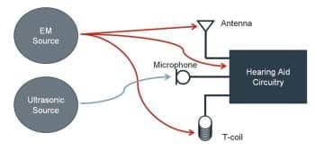
Figure 1. The four basic paths for interference to enter into a wireless digital hearing aid.
Intentional radiators. Intentional radiators are devices that radiate (or transmit) electromagnetic energy on purpose in order to send information-bearing signals. Examples include television and radio transmissions, global positioning systems (GPS), cell phones, wireless Internet networking systems, and many other applications. The EM energy that is transmitted has narrow bandwidth in order to save power and to coexist with other devices that transmit electromagnetic energy simultaneously. For example, in the United States, the Federal Communications Commission (FCC) segmented the spectrum of EM frequencies from 3 kHz to 300 GHz into narrower bands to ensure that transmissions from different devices do not interfere with one another during simultaneous operations.
The FCC has required licensing for certain frequency bands that are classified for use with particular types of transmitters. Frequency bands that are allowed for unlicensed use have strict transmission power limits to prevent interference among devices. Examples of common household wireless devices that utilize unlicensed portions of the EM spectrum include wireless computer networks (WLAN), Bluetooth devices, and baby monitors. When a number of these devices are operating in close proximity, the potential exists for them to interfere with one another. Wireless hearing aids that use the same 2.4 GHz ISM (Industrial, Scientific, Medical) band as WLAN and Bluetooth networks could potentially experience interference, as well.
Unintentional radiators. Unintentional radiators of EM energy do so as a by-product of their use of electricity. For example, household appliances such as refrigerators and washing machines typically have electric motors that convert electric current into electromagnetic fields for the purpose of rotating some piece of machinery (ie, the compressor on a refrigerator or the drum on a washing machine). These household appliances are not using the EM fields to transmit a signal, but they emit EM energy unintentionally nonetheless that can interfere with other electrical devices (such as an analog radio).
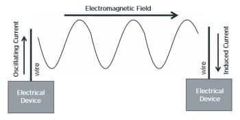
Figure 2. An electric current in a device can generate an electromagnetic field, which in turn can induce an electric current in a nearby device.
Examples of other sources of unintentional interference could be electrical power lines, transformers, fluorescent lights, switching power supplies, computers, and computer monitors. Household sources include irons, refrigerators, toasters, hair dryers, TVs, coffee machines, electric ovens, and even light bulbs. These devices can emit widely variable amounts of EM noise with different characteristics. Devices that contain a microprocessor or other high frequency digital circuits typically emit EM energy concentrated around a number of distinct frequencies that are closely linked to the signaling frequencies, clock, and crystal frequencies. A circuit breaker is more prone to emit a broadband EM noise. Electrical power mains are notorious sources of EM energy at 60 Hz.
Special attention should be paid to microwave ovens. They are designed to emit a high-level 2.45 GHz signal within the oven itself but are shielded to prevent most of this energy from leaking outside of the oven. However, some of the energy does leak out and can interfere with other devices that operate in this 2.4 GHz frequency region such as WLAN and Bluetooth. The wearer should be counseled on the potential for interference and move farther away from the potential EM source if needed.
Figure 1 shows the paths in which EM interference may occur in a wireless digital hearing aid. The following is a more detailed description of the impact of interference through each of these four routes. We will first address EM interference in all hearing aids and in wireless aids, along with a discussion of how hearing aid manufacturers address these issues, before turning to the issues of telecoil and ultrasonic interference.
#1) Electromagnetic Interference in All Hearing Aids (Wireless and Non-Wireless) as With Cell Phones
The circuitry of a hearing aid is vulnerable to interference from radiated electromagnetic energy because the electronic circuit components can act as antennae to pick up the EM energy and pass it along as noise. The frequency at which an EM field oscillates is an important factor in generating interference in a hearing aid. The higher the frequency of oscillation (thus, shorter wavelength), the more significant is the effect of the voltage change on the very small components used in hearing aids.2
While any EM device can produce interference in a hearing aid, digital cell phones have been a significant source of problems in the past. This is due to the high frequency and modulation of the generated EM field and the proximity to the hearing aid when held against a person’s ear. When the EM field produced by the phone’s antenna is within centimeters of the user’s hearing aid, a strong electric current and voltage is induced on the hearing aid circuitry.
Furthermore, because the EM field of a digital cell phone is modulated at a much lower frequency, it can cause audible interference in a hearing aid. The type and amount of interference depends on the type of modulation used. For example, GSM (Global System Mobile, commonly used in the United States and worldwide) cell phones use a digital modulation scheme where a transmitted pulse is sent every 4.62 ms. This corresponds to a modulation frequency of 217 Hz and can be heard as a loud buzz when the cell phone is placed close to the hearing aids. Figure 3 shows the modulation pulses seen in a GSM cellular phone.
Fortunately, better shielding of hearing aid circuitry to EM energy, along with hearing aid-compatible cellular phones (better placement of cellular telephone antennae and lower transmission power), has largely mitigated this type of interference problem. Currently, digital cell phones and hearing aids are rated on a 1 to 4 scale (M4> or T4 being the best; M stands for microphone compatibility and T stands for t-coil compatibility) depending on their compatibility.3 For example, all Widex hearing aids carry a M3/T3 or M4/T4 rating.
#2) Interference in Wireless-Connected Hearing Aids
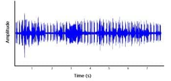
Figure 3. GSM interference from a cell phone. Listen to this sound here.
As more hearing aids use wireless connectivity for communication with external devices, it is possible for bands of EM noise in the environment to mask the transmitted EM signals. This prevents the antenna from receiving the transmitted information correctly (if at all), impacting the quality of the wireless communication. The consequences of the interference vary depending on what is being transmitted, number of EM interferers, characteristics of the interferers (power, frequency, modulation scheme), as well as the proximity of the devices to the hearing aids.
Interference in short-range transmission. Most digital wireless hearing aids use a short-range transmission (3 to 11 MHz) and a long-range transmission (2.4 GHz).1 For example, in the WidexLink, short-range transmission is achieved through the use of induction with a 10.6 MHz band carrier, while the long-range transmission is through the use of a 2.4 GHz carrier. Functions achieved through short-range transmission include inter-ear communication of parameter settings (such as compression, noise reduction, feedback, Zen, etc) at 21 times per second, short range audio streaming (between hearing aids, such as Phone+, and from streamers to hearing aids), remote control commands, and programming using the nEarCom. Another close-by EM source that uses a similar carrier frequency (10.6 MHz or 2.4 GHz) could potentially interfere with the integrity of the transmission.
If interference occurs when hearing aid setting information is being shared between the two aids (eg, inter-ear compression parameters), the latest settings will not be updated. This means that the hearing aids will continue to use the former settings, but no interruption of amplification will be noted by the wearer. To alert the wearer of such an occurrence, the Clear hearing aid has a verbal messaging system that announces “Partner check” when loss of inter-ear communication occurs. Once the interference source is removed (or communication reestablished), sharing of hearing aid data continues automatically.
If interference occurs during the use of the remote control, one would notice that the hearing aids are unresponsive (eg, pressing the volume button does not result in a corresponding change in loudness).
If interference occurs during wireless programming, the clinician would notice a slowing of the pace of programming (eg, setting the gain). In the worst case, a message indicating “communication failure” would be displayed on the computer screen to warn the dispensing clinician that wireless programming is not possible. The EM source in the vicinity that uses a similar carrier frequency must be moved farther away to restore communication. Also, making sure that the programming device (eg, nEarCom) is equal distance from each of the binaural hearing aids ensures consistent communication.
It is easier for the wearer to notice interference during audio streaming (eg, streaming audio between hearing aids in the Phone+ feature, or from the TV-Dex or M-Dex streamer to the hearing aids). In these cases, clicks, drop outs, and overall degradation of audio quality occur. Figure 4 shows a sample of the result of interference. Removing the interfering source (EM devices that use a 10.6 MHz carrier) generally improves the transmission.
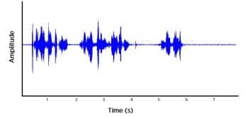
Figure 4. Example of interference of the audio signal in digital wireless transmission. Listen to this sound here.
Although EM interference from an external source can cause intermittent performance, a more common reason for intermittent performance is that the transmission distance between the hearing aids (or between the hearing aids and the streamer/programmer/remote control) is exceeded. Typically, a transmission distance of 1 m is allowed for all the hearing aids and streamer/remote/programmer configurations in order to keep the EM radiation as low as possible. Furthermore, the orientation of the antennae used in the hearing aids can affect sensitivity to the transmitted signal. Thus, bringing the hearing aids/streamer closer and/or reorienting the devices will lead to an improved communication.
Interference in long-range or far-field transmission. Most wireless hearing aids use a 2.4 GHz carrier in their long-range communication. This also includes the WidexLink wireless platform with the TV-Dex and the M-Dex1 where audio data are transmitted from the TV/cell phone to the hearing aids. Because there are a multitude of other long-range communication devices competing for the same frequency bandwidth, the potential for interference is greater with the long-range communication link. If interference occurs, the wearer will notice clicks, drop outs, and overall degradation of audio quality (see Figure 4). Removing oneself or increasing the distance from the interfering source may help to restore the communication.
Hearing Aid Designs That Minimize Interference
Bluetooth is a common technology that uses the 2.4 GHz carrier. When BT was first introduced, it was anticipated that several devices utilizing the same BT band (2.4 GHz) would be present in the same environment, causing potential interference.
In order for two devices to coexist using the same 2.4 GHz frequency band, a frequency hopping scheme was developed. In this scheme (called Frequency-Hopping Spread Spectrum or FHSS), the 2.4 GHz band is divided into 79 narrower channels, each with a 1 MHz bandwidth. The carrier frequency “hops” around these 79 channels continuously in order to avoid interference. Thus, it never stays at one fixed frequency channel. If a device attempts to use a channel that another device is already using, the device will hop to a different channel that is unoccupied. Thus, two or more devices would be able to coexist with one another without a noticeable loss of performance.

Figure 5. Example of the WLAN channels (802.11b), which can cause interference due to overlaps in adjacent channels.
Another device that commonly shares the same frequency band is the Wireless Local Area Network (WLAN) device typically used for wireless Internet connections. Like BT, WLAN also uses the 2.4 GHz band for transmission. Unlike BT, WLAN uses the Direct-Sequence Spread Spectrum (DSSS) technique that divides this frequency band into 14 channels, each with a 22 MHz bandwidth and a 5 MHz spacing between channels. WLAN stays in one channel and does not frequency hop. The purpose is to allow multiple wireless networks to operate within a close range of each other (eg, your own network and your next-door neighbor’s network). Figure 5 shows the overlapping channels used in a WLAN system. It suggests the possibility that adjacent WLAN channels will interfere with one another because they both share some of the same frequency range.
Commonly, BT and WLAN devices may operate within the same location. Interference can occur between them depending on the relative strength of each signal. As more devices using Bluetooth and WLAN are present in the same location, the likelihood of interference increases. Symptoms of interference for a WLAN device may be a slowdown in network speed. For example, downloading a music file takes much longer. A BT audio connection may begin to sound garbled or distorted in the presence of interference.
Both WLAN and BT are designed to fail gracefully (graceful degradation), meaning that the performance of each will slow down in the presence of interference instead of completely terminating the transmission. As indicated, long-range transmission technologies in hearing aids typically use a 2.4 GHz transmission; thus, some of the same techniques used by BT, such as frequency hopping, are applied to protect against interference while transmitting audio information over a long distance (within 10 m).
In addition, Kuk et al4,5 provided a discussion of additional considerations in the design of the WidexLink platform to minimize interference. These include:
- Frequent transmission of inter-ear data. The inter-ear features are updated at 21 Hz (or 21 times per second). This means the hearing aid settings are not only up-to-date, but also corrected very quickly if even a single transmission fails.
- Redundant transmission. Some data, such as hearing aid settings, are transmitted from the remote control in multiple packets. Each packet contains the same information. As long as one of the packets is received, information is transmitted successfully.
- High bit-rate. A high bit-rate means more information (ie, bits) is transmitted per second. In addition to ensuring that the audio transmitted is of a high resolution, it also means that any corrupted transmission may be compensated by the uncorrupted bits. In this case, it is worthwhile to note that the WidexLink has a 212 kbit/s bit-rate.
- Forward error correction (FEC). While interference increases the odds of transmission errors, many errors can be anticipated in advance. Realizing the potential errors allows Widex engineers to add a large proportion of error correction codes into the transmitted packet so the errors can be corrected instantly.
- Patent-pending over-sampling transceiver. As indicated in Kuk et al,5 most transceivers sample the transmitted bit twice to identify if it is a “1” or “0.” While this approach is sufficient for information transmitted without any interference, it may not be sufficient when there is interference (EM noise). In the WidexLink, each bit is sampled five times to ensure that it is correctly identified.
- Graceful degradation. When interference/errors cannot be avoided, instead of stopping the transmission or waiting for the correct data, WidexLink uses graceful degradation so that there will not be complete drop outs. This improves the overall sound quality of the transmitted signal, because hissing, crackling, and pops are minimized.
How Well Does it Work? The Concept of EM Compatibility
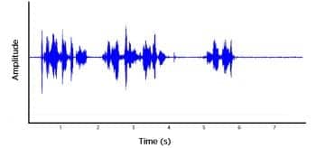
Figure 6. An example of electrical line (60 Hz) interference through the t-coil, as when passing by an electrical main or power pole. Listen to this sound here.
Because wireless hearing aids have both a transmitting and a receiving antenna (or combined antenna), it is possible that their performance may interfere with, or be interfered by, other EM devices in the surroundings. The suitability of an EM device to coexist with other devices in a typical operating environment is referred to as electromagnetic compatibility (EMC).
EMC considers the EM radiation safety of the device, as well as the performance of the device. In the United States, all EM devices (including cell phones, iPads, and wireless hearing aids) have to undergo standard EMC testing following established protocols and guidelines. For example, the Food and Drug Administration (FDA) has established a number of protocols6 that require emissions testing of all EM devices. Wireless hearing aids are also evaluated by the Federal Communications Commission (FCC), 47 CFR, part 15, subpart C. The American National Standards Institute (ANSI) has a guideline for measuring EMC between wireless cell phones and hearing aids.3 The FDA has recommended the use of the IEC 60601-1-2:2007 standards in measuring the EMC safety and compatibility of wireless hearing aids. Thus, wireless hearing aids—like any other EM devices—have to be evaluated for EMC with the appropriate standards. More details will be discussed in a future paper that focuses on the potential radiation safety issues of wireless hearing aids.
While the EMC testing with the recognized standards ensures the safety of the wireless hearing aids, their ability to coexist with other EM devices is evaluated semi-formally (because there is no formal protocol) through coexistence studies. In these studies, the wireless hearing aids and their accessories (Dex, programmer, etc) are exposed to other active EM devices at a typical separation. The performance of the wireless hearing aids is monitored to observe if any interference in performance occurs. In principle, any EM devices that have a likelihood of occurring in the wearer’s daily listening environments should be included.
For example, prior to the introduction of its Clear440 hearing aids, Widex conducted an exhaustive evaluation in which the hearing aids and its accessories were exposed to different EM environments. A list of the different wireless devices tested during five series of experiments, along with the devices’ carrier frequencies, is provided in Table 1 of the online version of this article. In all cases, no signs of any interference were noted. This suggests that the Clear hearing aids and their accessories can be used in the presence of other EM devices without being affected by the other EM devices.
However, there is a caveat. Despite the high compatibility, the results do not mean that the hearing aids are immune from all EM interference; they simply mean that the likelihood of interference from the evaluated devices in a typical user condition is low. Professionals and consumers are encouraged to ask manufacturers of wireless hearing aids for such documentation for assurance when selecting wireless hearing aids.
#3) Telecoil Interference
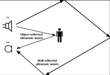
Figure 7. Ultrasonic occupancy sensors are often used in automatic lighting systems.
The t-coil consists of a wire that has been wound many times to form a coil. When this coil is in the presence of an EM field, a current can be induced in the coil and it may be heard as a sound by the hearing aid user. The t-coil is essentially a wide-band analog antenna that receives analog EM signals instead of digitally coded (Frequency Shift Keying, FSK) EM signals. Note that, since a t-coil is simply a “receiving” device, it does not radiate EM energy; thus, it does not pose any degree of radiation risk. However, since it is a “receiver,” it is possible for the t-coil to pick up unwanted EM energy.
One common type of noise received by t-coils comes from electrical power mains that power electrical devices plugged into an outlet. This includes any device that uses electricity, such as fluorescent lights, a computer monitor, etc. Because the electric power supplied in the United States alternates at a frequency of 60 Hz, electric power lines produce a corresponding magnetic field that oscillates at 60 Hz. This unwanted noise can be picked up by the t-coil and heard by the wearer as a buzzing sound (Figure 6).
In addition to picking up unwanted 60 Hz power line noise, a common complaint about the successful use of t-coils is that the inductive signal is noisy or not loud enough. Often, this has to do with the orientation of the t-coil in the EM field,7 since the maximum sensitivity is reached when the t-coil is perpendicular to the EM field. Proper reorientation of the t-coil is often sufficient to yield a cleaner, louder inductive signal. Applying EM shielding to hearing aid components reduces the amount of unwanted EM fields to which the components are exposed, thus reducing the amount of interference introduced into a hearing aid.
#4) Ultrasonic Interference
Ultrasonic sound is another type of signal that is increasingly used in our environments. Ultrasonic interference differs from EM interference because ultrasonic signals are acoustic signals that have a frequency higher than the upper limit of human hearing, whereas EM signals are oscillation of electromagnetic fields.
Increasingly, more devices are using ultrasonic sounds in a sensor to detect objects. The most familiar use of this technology is ultrasound pictures taken of infants in their mother’s womb (sonogram). Another application of ultrasonic sounds is “occupancy sensors.” In an effort to conserve electricity, many buildings are integrating occupancy sensors to automatically control the lighting. These sensors are typically mounted on the wall or ceiling of a room where ultrasonic audio is directed into the room to detect changes in the environment. If a person enters the room equipped with the sensor, the sensor detects a change in the reflection pattern for the ultrasonic sound (Figure 7) and turns on the lights.
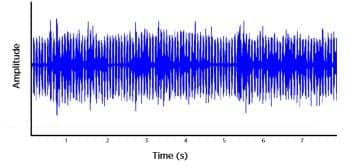
Figure 8. Ultrasonic interference. Listen to this sound here.
Ultrasonic sounds can lead to distortions—such as an intense pulsating buzzing noise (see Figure 8)—in a digital hearing aid. This distortion is due to aliasing, which can occur during the analog to digital conversion process. When sampling an analog signal for conversion into a digital format, the rate at which the samples are acquired limits the maximum frequencies that can be reliably gathered. Frequencies that are greater than half of the sampling rate will enter the A/D conversion process as aliasing errors. For example, an input signal at 36,000 Hz will appear as a 4000 Hz alias signal for a sampling frequency at 32,000 Hz. This would be heard as a buzzing to the hearing aid wearer.
To minimize aliasing errors, it is recommended that the sampling frequency be at least twice the highest audio frequency to be digitized (commonly called the Nyquist sampling theorem). For Widex hearing aids, which have a sampling frequency of 32 kHz and thus an audio bandwidth of 16 kHz, this would mean that any sounds with a frequency above 16 kHz may enter the A/D conversion process and be represented by some other frequency. Since we know that the system is sampling at 32 kHz, a low-pass filter may be added to prevent frequencies above 16 kHz from entering the A/D conversion process, thus reducing the potential for aliasing errors.
This reduces the problem of aliasing for most ultrasonic frequencies. However, as is the case with any filter, filtering only attenuates the input signal by a finite amount. If the ultrasonic signal is too intense, some aliasing may still occur and be audible.
This is an emerging area of concern, and hearing aid designers are working feverishly to achieve greater reduction or elimination of ultrasonic interference for future devices. At this point, hearing aid users who experience ultrasonic interference should be counseled on the source of the interference to determine the best strategy to handle the situation. In some cases, it is possible that the ultrasonic emitter be turned on/off conveniently to allow the hearing aid wearer to stay in the room without interference.
Conclusion
It is sometimes difficult to determine the exact source of interference, but it is helpful if the patient can describe the environment where interference is noted. For example, the patient may complain of lower audio quality while watching TV through a hearing aid TV streaming device. It would be beneficial to determine what other devices that use a 2.4 GHz transmission frequency might be nearby (eg, WiFi, BT devices, or a microwave oven). The patient may complain of buzzing noises in certain rooms of an office building that utilizes ultrasonic security sensor systems. In this case, the building manager may need to be contacted to inquire about potential sources of ultrasonic interference.
By recognizing potential sources of interference, clinicians and patients can better understand how to minimize them. Complete immunity to all forms of interference is almost impossible to achieve; however, with proper design and adequate instructions, the negative effects of interference in hearing aids can be minimized.
References
- Kuk F, Crose B, Kyhn T, et al. Digital wireless hearing aids: Part 3: Audiological benefits. Hearing Review. 2011;18(8):48-56. Accessed November 5, 2011.
- Levitt H. The nature of electromagnetic interference. J Am Acad Audiol. 2001;12:322-326.
- American National Standards Institute (ANSI). ANSI C63.19 (2007) for Wireless Communications Devices and Hearing Aids. Washington, DC: ANSI; 2007.
- Kuk F, Crose B, Korhonen P, et al. Digital wireless hearing aids: Part 1: A primer. Hearing Review. 2010;17(3):54-67. Accessed November 5, 2011.
- Kuk F, Korhonen P, Crose B, et al. Digital wireless hearing aids: Part 2: Considerations in developing a new wireless platform. Hearing Review. 2011;18(6):46-53. Accessed November 5, 2011.
- US Food and Drug Administration. FDA De novo decision summary on Widex Clear C4-PA wireless air conduction hearing aid (2011). Available at: www.fda.gov/AboutFDA/CentersOffices/CDRH/CDRHTransparency/ucm232269.html. Accessed October 31, 2011.
- Ross M. Telecoils: issues and relevancy. Semin Hear. 2005;26(2):99-108.
Citation for this article:
Crose B, Kuk F, Bindeballe H. Digital Wireless Hearing Aids, Part 4: Interference. Hearing Review. 2011;18(13):30-39.


